



Contents: Petrol models ↡ Diesel models ↡
Petrol models
The corresponding illustrative material is presented in the illustration Steering drive organization diagram and the illustrations below, to which all references in the text refer.
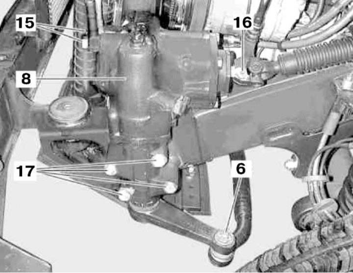
Steering gear installation details on petrol models
6 - Steering knuckle; 8 - Steering mechanism; 15 - Hollow bolts of nipple connections; 16 - Steering shaft mounting bolt; 17 - Steering gear assembly mounting bolts
1. Using a suitable puller, press the transverse rod (9) out of the steering arm (7).
2. On models equipped with 113 series engines, remove the left headlight assembly (see Chapter On-board electrical equipment) and steering pump (see Section Removal and installation the steering pump).
3. Remove the radiator (see Chapter Cooling, heating, ventilation and air conditioning systems).
4. Remove the power steering fluid cooling line (14) (see Section Removal and installation of the power steering fluid cooling line).
5. Unscrew the hollow bolts (15) of the union connections and disconnect the hydraulic lines from the steering gear assembly - drain the hydraulic fluid into a previously prepared container.
6. Remove the bolt (16) and disconnect the lower universal joint of the steering shaft from the input shaft of the steering gear.
7. Unscrew the mounting bolts (17) and remove the steering gear assembly.
8. Installation is carried out in the reverse order. Do not forget to check the levels of working fluids and, if necessary, make the appropriate adjustments.
9. Finally, clear the memory of the on-board diagnostic system processor (see Chapter Engine electrical systems) and adjust the front wheel alignment angles (see Section Suspension Geometry).
Diesel models
Models 463.323 (M612)
The corresponding illustrative material is presented in the illustration Steering drive organization diagram and the illustrations below, to which all references in the text refer.
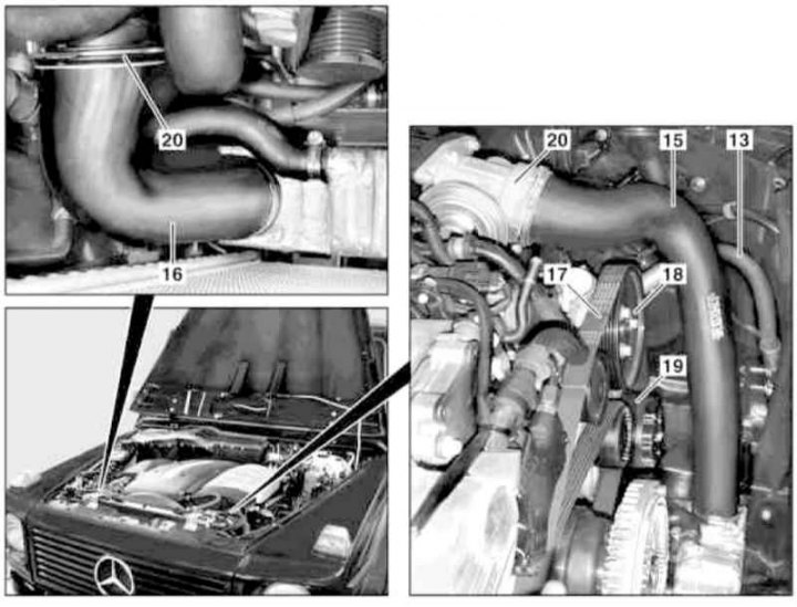
Preparing to remove the steering pump (models 463.323)
13 - Pressure line; 15 - Left air duct; 16 - Right air duct; 17 - Auxiliary drive belt; 18 - Drive pulley; 19 - Compressor K/V; 20 - Fastening clamp
1. Remove the cylinder head cover trim panels.
2. Remove the viscous coupling of the cooling system fan drive (see Chapter Cooling, heating, ventilation and air conditioning systems).
3. Remove the cooling system radiator (see Chapter Cooling, heating, ventilation and air conditioning systems).
4. Remove the left (15) and right (16) air intake duct sleeves.
5. Remove the accessory drive belt (see Chapter Engine).
6. Remove the pulley (18) of the steering pump drive (11) (see Section Removal and installation the steering pump).
7. Pump out the fluid from the power steering reservoir.
8. Remove the A/C compressor (19) and, without disconnecting the refrigeration lines, move it to the side.
9. Remove the left front wheel.
10. Remove the left headlight (see Chapter On-board electrical equipment).
11. Using a suitable puller, press the transverse rod (9) out of the steering arm (7).
12. After completing the procedures described in paragraphs 5 through 7 for gasoline engines, remove the steering gear assembly (8).
13. Installation is carried out in the reverse order. Finally, do not forget to adjust the front wheel alignment angles (see Section Suspension Geometry).
Models 463.333 (M628)
The corresponding illustrative material is presented in the illustrations Steering pump installation details (models with M628 engines) (1 of 2), Steering pump installation details (models with M628 engines) (2 of 2) and the illustrations below, to which all references in the text refer.
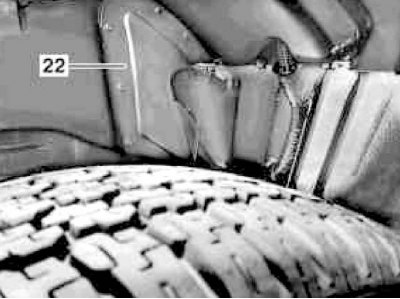
Location of cover (22) in wheel arch
1. Jack up the car and place it on supports.
2. Remove the left front wheel.
3. Remove the wheel arch protection liner.
4. Remove the left headlight (see Chapter On-board electrical equipment).
5. Remove the air cleaner (1).
6. Remove the left air intake (2).
7. Remove the four screws, take out the dipstick and unscrew the oil filler cap, then remove the trim panel (4).
8. Remove the radiator (see Chapter Cooling, heating, ventilation and air conditioning systems).
9. Remove the oil filter housing (20).
10. Pump out the fluid from the power steering reservoir (7).
11. Remove the reservoir (7) (see paragraphs 13 and 14 in Section Removal and installation the steering pump).
12. Remove the accessory drive belt (14) from the drive pulley (10) of the pump assembly (11) (see paragraph 15 in Section Removal and installation the steering pump).
13. Loosen the air duct (21) on the cylinder head.
14. Remove the cover (22) in the wheel arch.
15. Remove the turbocharger heat shield.
16. Remove the left lower air duct (17).
17. Using a suitable puller, press the tie rod out of the steering arm.
18. After performing the procedures described in paragraphs 5 through 7 for gasoline engines, remove the steering gear assembly (8).
19. Installation is carried out in the reverse order. Do not forget to check the levels of working fluids and, if necessary, make the appropriate adjustments.
20. Finally, clear the memory of the on-board diagnostic system processor (see Chapter Engine electrical systems) and adjust the front wheel alignment angles (see Section Suspension Geometry).