
Note. All self-locking fasteners must be replaced without fail!
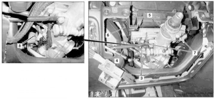
Installation details of the electrically adjustable steering column (1 of 3)
3 - Wiring connectors; 4 - Remote pipe; 5 - Column sleeve; 6 - Bearing bracket; 7 - Top bolt; 8 - Bottom bolt
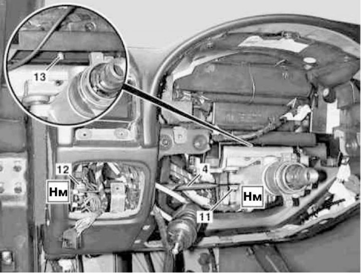
Installation details of the electrically adjustable steering column (2 of 3)
4 - Remote pipe; 11, 12 - Screws; 13 - Pins
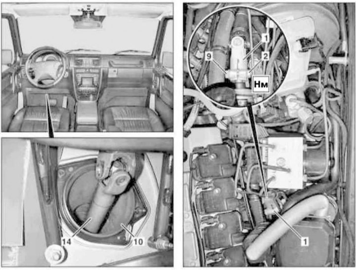
Installation details of the electrically adjustable steering column (3 of 3)
1 - Central universal joint; 2 - Nut; 9 - Screw; 10 - Rubber boot; 14 - Steering shaft
1. On models of the corresponding configuration (code ET2) activate the service mode of the TELE AID emergency call system (see Section Activation / deactivation of the service mode of the TELE AID emergency call system).
2. Turn on the auxiliary battery and connect it to the standard battery, then disconnect the negative cable from the latter.
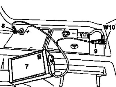
7 - Auxiliary battery
8 - Module positive wire terminal
9 - Terminal of the negative wire of the module
W10 - Battery Ground
3. Turn straight and remove the steering wheel (see Section Removal and installation of a steering wheel).
4. Remove the instrument cluster (see chapter Body).
5. Remove the cover on the left under the instrument panel.
6. 7 Remove the ignition lock assembly (EIS) (see chapter Onboard electrical equipment).
7. Remove the steering column cover.
8. If equipped, remove the knee brace.
9. Disconnect connectors (3) wiring.
10. Remove the switch for switching the modes of operation of lighting devices (see chapter Onboard electrical equipment).
11. Turn out bolts (12 and 11).
12. Remove the remote pipe (4).
13. Turn out the top (7) and lower (8) bolts.
14. Give the nut (2) and remove the bolt (9) central cardan joint (1).
15. Prying off, remove the hinge (1) from the steering shaft (14).
16. Pulling inside the passenger compartment, remove the sleeve of the steering column (5), - try not to damage the anther (10).
17. Installation is in reverse order - do not forget to seat the pin (13) into the socket of the carrier bracket (6).
18. Deactivate the service mode of the TELE AID system if equipped accordingly.
19. In conclusion, clear the memory of the processor of the on-board self-diagnosis system (see chapter Engine Electrical Systems).