
Removing
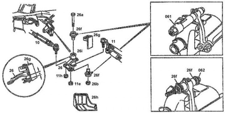
Pendulum arm installation details
1. Separate from the pendulum arm (26) tie rod (10).
2. Separate from the pendulum arm (26) medium thrust (11).
3. Remove the heat shield (26h).
4. Give the nut (26b), remove the screw (26a) and remove the swingarm (26) complete with bearing ring (26i).
5. Pry off the sealing lips with a screwdriver and remove the sleeve from the bearing ring.
6. Using a puller (061) REF 129 589 00 33 00 remove the rubber cushion (26f).
Installation
1. Installation is carried out in the reverse order. The rubber cushion must be seated as far as it will go using a special tool (062) № 201 589 08 43 00.
2. Properly adjust the mounting dimension a of the pendulum arm assembly with the bearing ring (a = 22.7 mm).
3. Replace all self-locking fasteners.
4. Tighten the self-locking nut securing the pendulum arm to the bearing with a force of 120 Nm.
Note. With the correct position of the ball joint, the adjustment position can vary by a maximum of 5 mm.