



Contents: Disassembly ↡ Assembly ↡
Engine cylinder block parts M 102
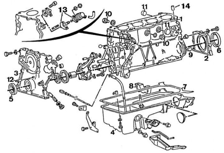
1 - cylinder block; 2 - Crankshaft rear oil seal holder; 3 - timing cover; 4 - oil pan; 5 - front crankshaft oil seal; 6 - rear crankshaft oil seal; 7 - oil pan gasket; 8 - main bearing cap; 9 - centering pin; 10 - cork; 11 - plug; 12 - pointer for setting the ignition timing; 13 - fuel pump; 14 - mounting pin
Disassembling the cylinder head of a 4-cylinder engine
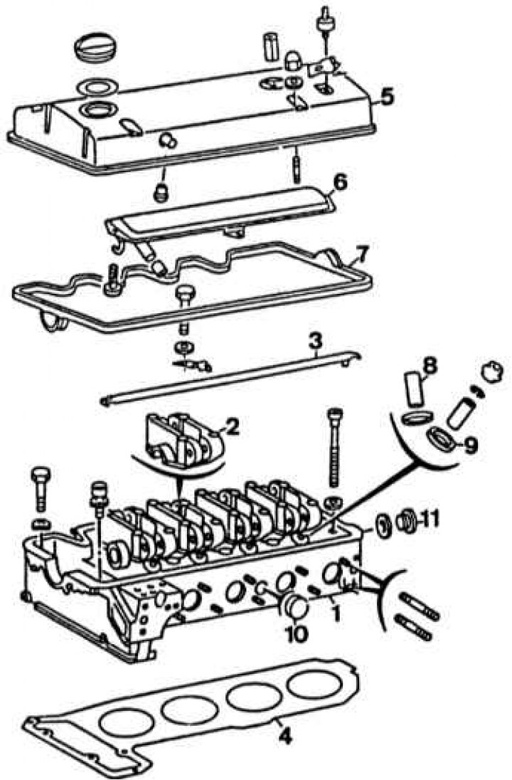
1 - cylinder head; 2 - camshaft bearing housing; 3 - oil line; 4 - cylinder head gasket; 5 - cylinder head cover; 6 - oil deflector; 7 - cylinder head cover gasket; 8 - valve guide bushing; 9 - valve seat; 10 - plug; 11 - cork
Disassembly
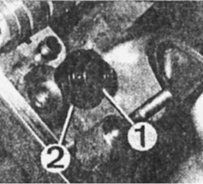
Disassembling the cylinder head of a 4-cylinder engine
1 - valve oil deflector cap
2 — valve spring plate
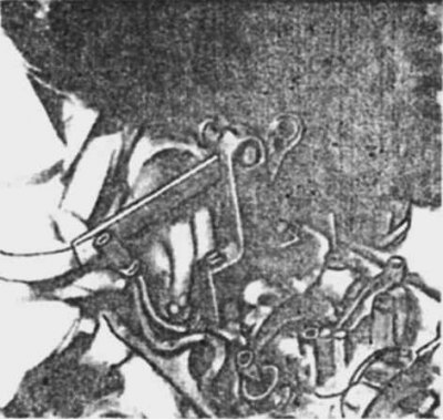
Removing valve crackers on the cylinder head of a 4-cylinder engine
1. Remove the cylinder head.
2. Remove the exhaust manifold with the gasket.
3. On fuel injected engines, remove the intake manifold together with the air flow meter and fuel metering assembly.
4. On engines with hydraulic valve lifters, gradually loosen the camshaft bearing housing mounting bolts.
5. Remove the tappet plates and mark the tappets and their seats.
6. Remove the camshaft from the cylinder head supports.
7. Release the valves from the crackers by compressing the valve spring with a special device.
8. On an engine with adjustable valve clearances, unscrew the adjusting bolts as far as possible.
9. Gradually loosen the rocker arm axle bearing mounting bolts.
10. Remove the plate, spring, take out the valve and mark its position in the cylinder head.
11. Remove the oil deflector cap from the valve guide.
12. Remove the spring support washer.
13. Check the condition of the valves, valve seats and guides, as well as the clearance between the guides and valve stems.
14. Clean the cylinder head and removed parts. On engines with hydraulic valve lifters, check the rocker shaft oil passages (ball check valve condition).
15. Eliminate any faults found (for dimensions, see the Design and Specifications subsection — Cooling system).
16. After grinding or re-machining, thoroughly clean the cylinder head seats and bores.
17. Loosen the rocker arm axle support mounting bolts and remove the rocker arm axle using the M8 bolt.
18. Check the condition of the axle, rocker arm and lubrication channels.
Assembly
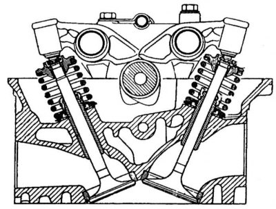
Cross-section of the cylinder head of M 102 engines with hydraulic compensation of thermal clearances in the valve drive
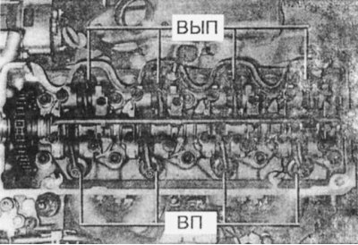
Valve arrangement on the M 102 engine
VYP - exhaust valves
VP - intake valves
1. Press new valve stem seals onto the valve guides.
2. Insert the valves into the guide bushings, install the springs and spring plates.
3. Using a special tool to compress the spring, install the valve crackers.
4. On engines with hydraulic lifters, install the lifter plates.
5. Assemble the rocker arm axle stands with the rocker arms and axles, ensuring that the axle channels match the mounting bolt holes.
6. Place the camshaft in the cylinder head supports and install the rocker arm axle supports in their original place.
7. Screw in the camshaft bearing housing mounting bolts and tighten them gradually to the specified torque (see subsection Design and specifications — Cooling system).
8. Turn the camshaft to the position corresponding to the combustion phase in the first cylinder (the valves should be closed and the mark on the camshaft should be against the edge of the cylinder head).
9. Install the intake manifold and exhaust manifold.
10. Further assembly is carried out in the reverse order of disassembly.
11. Install the cylinder head.