



Contents: Removal ↡ Installation ↡
Note: Remove the cylinder head when the engine is cold
Removal
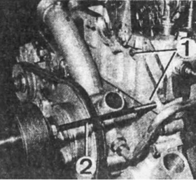
Removing the cylinder head of the M 102 engine
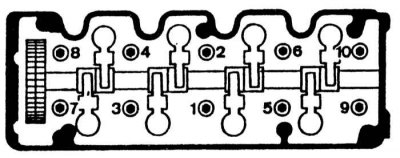
Tightening order of cylinder head mounting bolts for M 102 engine |
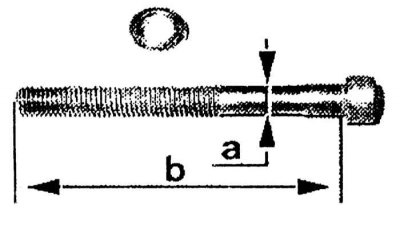
Checking the cylinder head mounting bolts a — diameter b — length |
1. Disconnect the ground wire from the battery.
2. Lift the hood vertically upwards.
3. Remove the air filter with the cold air intake.
4. On vehicles with a body position regulator, unscrew the bolts securing the pump without disconnecting the hoses. Move the pump to the side.
5. Drain the coolant.
6. Disconnect the connectors from the coolant temperature sensor, carburetor and injection system components.
7. Disconnect the heater hoses, the radiator supply hose, the carburetor fuel hoses, and on vehicles with an injection system, disconnect the fuel supply and drain hoses from the pressure regulator and fuel quantity distributor.
8. Disconnect the vacuum hoses.
9. Disconnect the throttle return spring.
10. Disconnect the throttle actuator rod from the lever.
11. Remove the intake manifold booster.
12. Remove the oil dipstick and close the dipstick tube with the plug.
13. On vehicles with air conditioning, disconnect the air conditioning system pipes from the cylinder head.
14. On vehicles with automatic transmission, unscrew the bolt securing the oil dipstick bracket to the cylinder head and disconnect the drive cable from the throttle rods.
15. Unscrew the ground wire clamp.
16. Depending on the year of vehicle production, loosen and remove the alternator drive belt or accessory drive belt.
17. Loosen the bolts securing the muffler inlet pipe to the exhaust manifold and separate them.
18. Disconnect the high-tension wire bundle from the spark plugs.
19. Remove the spark plugs.
20. Remove the ignition distributor cover with the wire harness.
21. Turning the crankshaft by the pulley, bring the piston of the 1st cylinder to TDC.
22. Unscrew the chain tensioner plug.
23. Remove the sealing ring and spring.
24. Apply marks of relative positions on the chain and on the camshaft depending on the engine model.
25. Lock the camshaft from turning by placing a 24 mm wrench on the flats.
26. Remove the chain guide.
27. Remove the chain from the camshaft sprocket and hold it in a position that prevents it from slipping off the crankshaft sprocket.
28. Remove the camshaft sprocket by unscrewing the mounting bolt.
29. Loosen the cylinder head mounting bolts in the reverse order of tightening.
30. Disconnect the cylinder head from the gasket and block and remove it together with the pipes.
31. Thoroughly clean the mating surfaces of the cylinder head and block. Do not clean the mating surface of the cylinder head. Take measures to prevent contaminants from entering the head channels.
32. Check the condition of the removed parts. Check the flatness of the mating surface of the cylinder head. Eliminate any faults found. Replace the cylinder head mounting bolts if necessary.
Installation
Before installing the cylinder head, make sure all parts are clean. Check the pull-out of the mounting bolts. Replace all gaskets.
1. Place the gasket with the lettering facing the cylinder head. Make sure that the mating surfaces of the cylinder head, block and gasket are dry and free of grease.
2. Lubricate the threads and bearing surface of the cylinder head bolts with engine oil.
3. Install the cylinder head and screw in the mounting bolts.
4. Tighten the bolts in the order shown in the figure.
5. To tighten the bolt, place the wrench on the bolt head so that it is directed along the longitudinal axis of the engine, and turn it 1/4 turn until it is perpendicular to the longitudinal axis of the engine.
6. Install the camshaft drive chain tensioner.
7. Place the chain on the camshaft sprocket, ensuring that the timing marks are aligned.
8. Tighten the sprocket mounting bolts.
9. Insert the chain tensioner into the socket and install the spring.
10. Check the timing adjustment.
11. Install the cylinder head cover.
12. Install the interference suppression screen, drive plate and distributor rotor on the engines.
13. Screw the spark plugs into the cylinder head.
14. Connect the ignition wire harness and install the ignition distributor cover.
15. On the M 102 engine, connect the vacuum hose.
16. Connect the exhaust pipe to the exhaust manifold.
17. Depending on the year of manufacture of the vehicle, put on the alternator drive belt or the multi-groove accessory drive belt and adjust its tension.
18. Depending on the vehicle configuration, tighten the automatic transmission oil dipstick tube bracket mounting bolt.
19. Depending on the vehicle configuration, connect the air conditioning hoses.
20. Install the dipstick tube and insert the dipstick.
21. Install the intake manifold booster.
22. Attach the throttle actuator return spring.
23. Connect the vacuum hoses to the intake manifold.
24. Connect the fuel supply and drain hoses to the carburetor or to the pressure regulator and fuel quantity distributor of the injection system.
25. Connect the heater and cooling system hoses.
26. Connect the plug connectors.
27. Fill and bleed the cooling system.
28. On vehicles with a body position regulator, install a pump.
29. Install the air filter with cold air intake.
30. Connect the ground wire to the battery.