



Contents: Removal ↡ Installation ↡
On vehicles with disc brakes, the brake drum for the parking brake shoes is combined with the brake disc.
Removal
1. Mark the position of the rear wheels on the hubs with paint. This will allow you to install the balanced wheel in its original position during assembly.
2. Loosen the wheel mounting bolts. The car must stand on its wheels when performing this operation.
3. Place the car on jack stands, unscrew the wheel bolts and remove the rear wheels.
Warning! Jacking up a vehicle or placing it on jack stands can pose a risk of injury. Therefore, it is recommended that you familiarize yourself with the safety precautions set out in Chapter "Jacking up a car".
4. Release the parking brake.
5. Set the parking brake adjustment mechanism to its original position by unscrewing gear 1 of the mechanism with a screwdriver. The screwdriver for this operation is inserted into the hole of the wheel bolt (see illustration).
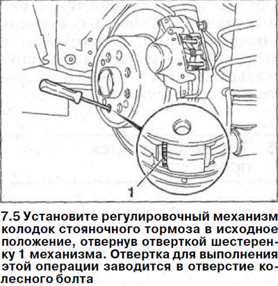
Attention! To set the adjustment mechanism of the parking brake shoes of the right wheel to the original position, the gear of the mechanism should be turned with a screwdriver from the bottom up, and the left wheel - from the top down.
6. Remove the rear wheel brake caliper, see the relevant chapter.
7. Remove the rear wheel brake disc, see the relevant chapter.
Attention! Remember or write down the installation position of the rear wheel parking brake components before dismantling them. When assembling, you can check them with the brake mechanism of the second wheel.
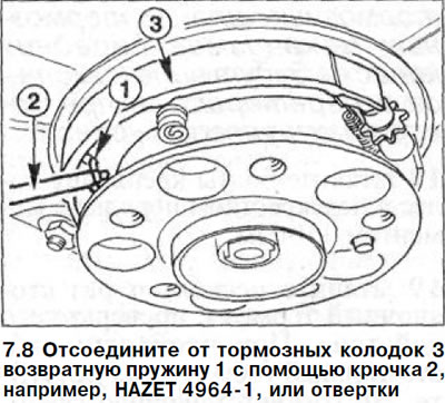
8. Disconnect the return spring 1 from the brake shoes 3 using a hook 2, e.g. HAZET 4964-1 (see illustration).
9. Turn flange 1 on the rear wheel hub so that one of the holes for the wheel bolt is positioned opposite the brake shoe pressure spring 2 (see illustration).
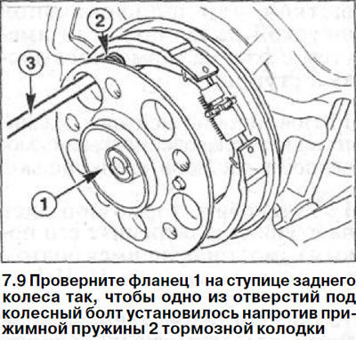
10. Insert tool 3, e.g. HAZET 2730, or a screwdriver into the hole in the wheel rim, compress the pressure spring 2, turn it by about 90° and remove the pressure spring (see illustration 7.9).
Attention! You can make a device for removing the pressure spring yourself. To do this, you need a rod of the appropriate diameter, to the end of which a handle is welded, forming the letter "T". At the other end of the rod, a slot up to 2.5 mm wide and up to 4 mm deep is cut.
11. Remove the second brake shoe pressure spring in the same way.
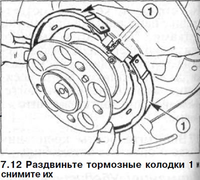
12. Spread the brake shoes 1 and remove them. Mark the installation position of the brake shoe adjuster. The mounting ring must face forward (see illustration).
13. Disconnect the return spring 4 from the brake pads and remove the adjusting mechanism 1-3 (see illustration).
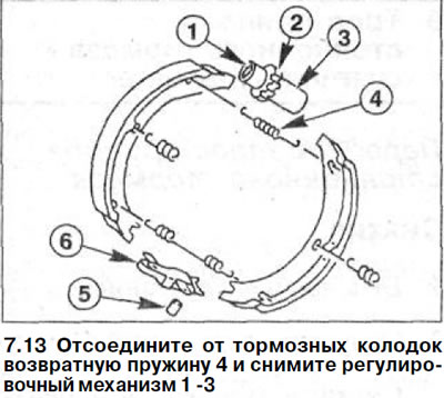
14. Press bolt 5 out of the brake shoe expansion bar 6 and disconnect the brake shoe drive cable end from it (see illustration 7.13).
Installation
If the brake shoe linings are burnt, it is recommended to replace the brake shoe return springs as well.
15. Lubricate the bearing surfaces of the brake shoe expansion bar with a thin layer of high-temperature paste, such as Liqui Moly LM-36, MOLYKOTE U or G-RAPID.
16. Disassemble the adjustment mechanism. Lubricate the thread of the pressure pin 1, as well as the cylindrical part of the adjustment gear 2 with high-temperature paste (see illustration 7.13).
17. Screw the pressure pin 1 (plunger) into the hole on the gear 2 and insert them into the spacer sleeve 3. In this case, screw the pressure pin in until it stops (see illustration 7.13).
18. Secure the parking brake cable with a bolt to the brake shoe expansion bar. Then feed the expansion bar to the support shield.
Caution: When installing the expansion mechanism, make sure that its moving part is facing upwards.
19. Install the adjusting mechanism in place between both brake shoes, with the pressure pin (plunger) facing forward in the direction of vehicle travel.
20. Fasten the upper return spring 4 to the brake shoes (see illustration 7.13).
21. Stretch the brake shoes connected to each other by the upper return spring and install them in place, securing them with a spreader bar.
22. Place the pressure spring 1 in place using the HAZET-2730 tool or screwdriver 2 through the hole in the wheel bolt. Then press it down and turn it 90° so that the spring is secured in the support cup. Make sure that the spring is seated correctly.
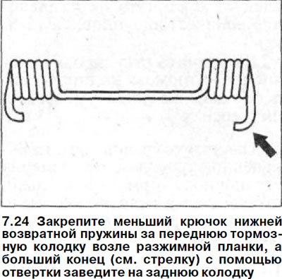
23. Install the second brake shoe pressure spring. Depending on the manufacturing option, both ends of the lower return spring differ in hook sizes.
24. Secure the smaller hook of the lower return spring to the front brake shoe near the expansion bar, and the larger end (see arrow in illustration) using a screwdriver, move it to the rear shoe.
25. Install the rear wheel brake disc, see the relevant chapter.
26. Install the caliper, see the relevant chapter.
27.. Install the rear wheels in accordance with the marks made during removal. Before doing this, lubricate the centering seat of the wheel disk on the hub with a thin layer of grease. Do not lubricate the wheel mounting bolts. Replace rusted bolts with new ones.
[Material created based on the website: www.mercedesman.ru]
28. Screw in the wheel mounting bolts and lower the vehicle.
29. Tighten the bolts in a crisscross pattern to 110 Nm.
30. Adjust the parking brake, see the relevant chapter.