
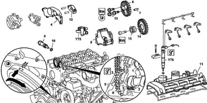
Installation details of the intermediate sprocket of the injection pump of the 612 series engine
1. Details of the installation of the intermediate sprocket of the injection pump of the 612 series engine are shown in the illustration, to which all references in the text refer.
2. Remove panels of finishing of a cover of a head of cylinders.
3. Remove nozzles (Y76) (see chapter Removal and installation of the fuel distributive highway and nozzles).
4. Remove the cylinder head cover (11).
5. Having turned the engine in the normal direction, bring the piston of the first cylinder to the TDC position - the camshaft alignment mark should be aligned with the mark on its bearing cap.
6. Block the intake camshaft (2) with a rod (3), threaded into the hole in the cover of the first bearing (A) and introduced into the hole of the gear shaft (5).
7. Remove the chain tensioner assembly (9) (see below)
8. Remove the front cylinder head cover (4) (see Section Removal and installation of the engine).
9. Remove the chain guide (12) (see below).
10. Remove injection pump (see chapter Removal and installation of the high pressure fuel pump (injection pump)).
11. Mark the position of the timing chain on the camshaft drive sprocket (6).
12. Screw off the asterisk (6) from the exhaust camshaft (1).
Note. Sprocket mounting bolts (13) must be replaced without fail.
13. Remove the sprocket (6), - try not to drop the guide pin (7).
14. Turn out a bolt of fastening of an intermediate asterisk (14) and remove the last assembly with the sleeve (15).
15. Installation is carried out in the reverse order - follow the correctness of the basic installation of the camshafts (see Section Setting the basic position of the camshafts).
16. Finally, start the engine and check for signs of oil and fuel leaks.
Chain tensioner
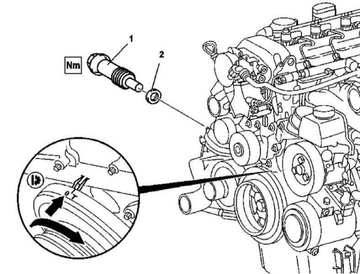
612 Series Timing Chain Tensioner Installation Details

612 Series Lower Timing Chain Guide Removal Preparing
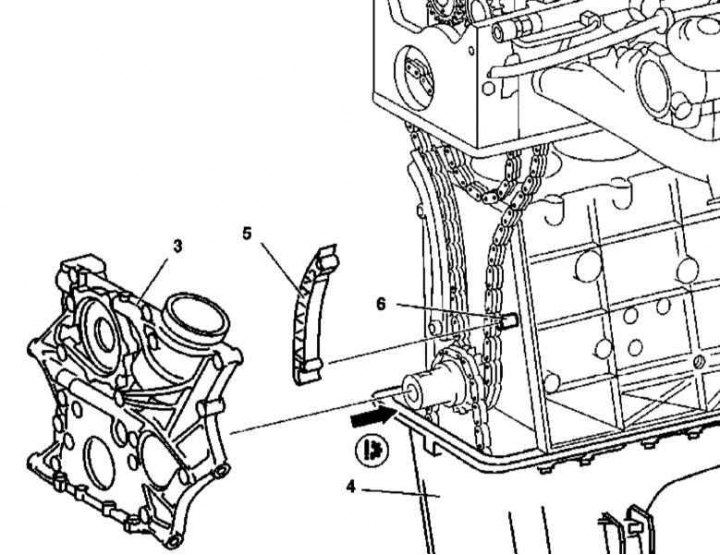
612 Series Engine Lower Timing Chain Guide Installation Details
3 - Timing drive cover; 4 - Oil pan; 5 - Guide; 6 - Bearing pin
1. Installation details of the 612 series timing chain tensioner are shown in the illustration, to which all references in the text refer.
2. Having turned the crankshaft in the normal direction, bring the engine to the TDC position of the piston of the first cylinder, the marks of the camshaft and its bearing caps must be aligned.
3. Remove the air intake.
4. Remove chain tensioner (1).
5. Installation is carried out in the reverse order - do not forget to replace the sealing element (2).
6. Lower chain guide
7. Illustrative preparation for removal and installation details of the lower timing chain guide of the 612 series engine are shown in the illustrations, to which all references in the text apply.
8. Remove the cylinder head (see Section Removing and installing the head (OK) cylinders).
9. Remove the timing cover (see Section Removing and installing timing covers).
10. Remove the bottom guide (5) from bearing pin (6).
11. Installation is carried out in the reverse order.
12. Finally, start the engine and check for signs of leaks. Also clear the memory of the on-board self-diagnosis module.
Chain guide on cylinder head
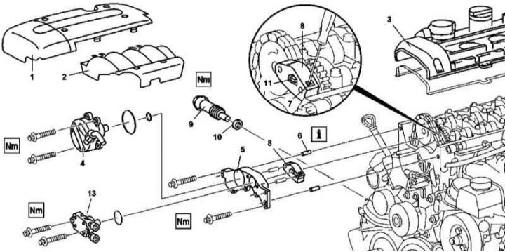
Details of installing the chain guide on the cylinder head of the 612 engine
1 - Panel trim cylinder head cover; 2 - Air distributor finishing panel; 3 - Cylinder head cover; 4 - Vacuum pump; 5 - Front cover of the cylinder head; 6 - Guide pin; 7 - Blocking ratchet; 8 - Upper chain guide; 9 - Chain tensioner; 10 - Sealing element; 11 - Drive element; 13 - Fuel pump
1. The details of installing the chain guide on the cylinder head of the 612 series engine are shown in the illustration, to which all references in the text refer.
2. Remove the cylinder head cover trim panel (1).
3. Having turned the crankshaft in the normal direction, bring the engine to the TDC position of the piston of the first cylinder, the marks of the camshaft and its bearing caps must be aligned.
4. Remove chain tensioner (9) (see above).
5. Remove the front cylinder head cover (5) (see Section Removing and installing timing covers).
6. Block the camshaft by inserting a special rod into the hole in its first bearing cap and threading it into the drive gear.
7. Unbolt the drive element (11) intake camshaft.
8. Remove the top chain guide (8).
9. Installation is carried out in the reverse order.
10. Finally, start the engine and check for signs of leaks.
Tension bar
Tension bar installation details on 612 series engine
6 — an Intermediate gear wheel of TNVD
Preparing to remove the tensioner bar from the 612 series engine
1. Illustrative preparation for removal and installation details of the tensioner bar on the 612 series engine are shown in the illustrations, to which all references in the text refer.
2. Remove the cylinder head (see Section Removing and installing the head (OK) cylinders).
3. Remove the timing cover (3) (see Section Removing and installing timing covers).
Note. The need to remove the oil pan (4) is missing, - try not to damage the sealing gasket of the pan.
4. Remove tension bar (7) from bearing pin (8).
5. Installation is carried out in the reverse order.
6. Finally, start the engine and check for signs of leaks. Also clear the memory of the on-board self-diagnosis module (see chapter Engine Electrical Systems).
M628
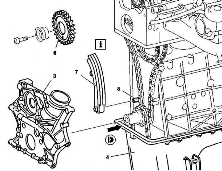
Intermediate sprocket injection pump
Installation details of the intermediate sprocket of the injection pump of the 628 series engine
1 - Final camshaft; 2 - Intake camshaft; 3 - Locking rod; 4 - Front cover; 5 - Intake camshaft gear; 6 - Camshaft drive sprocket; 7 - Guide pin; 8 - Chain tensioner; 9 - Sealing element; 10 - Cylinder head cover; 11 - Bolt; 12 - Intermediate sprocket of injection pump with injection angle advance clutch; 13 - Bushing; 14 - injection pump; 15 - Vacuum pump; 17 - Centrifuge; A - Hole; Y76 - Nozzle
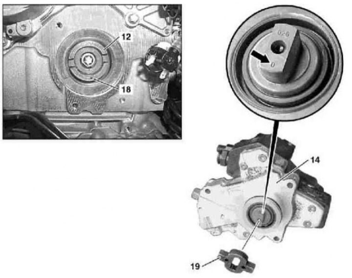
Installation details of the intermediate sprocket of the injection pump of the 628 series engine
12 - Intermediate sprocket of injection pump with injection angle advance clutch; 14 - injection pump; 18 - Nest; 19 - Floating injection angle advance clutch
1. Details of the installation of the intermediate sprocket of the injection pump of the 628 series engine are shown in the illustrations, which include all references in the text.
2. Remove cylinder head covers (10).
3. Remove the centrifuge (17).
4. Using special rods (3), threaded through the covers of the first bearings and the input holes of the drive gears (A), block the intake camshafts (2) both cylinder heads.
5. Remove chain tensioner (8) (see below).
6. Remove injection pump (14)
7. Remove the vacuum pump (15)
8. Remove front cover (4) cylinder heads (see Section Removing and installing timing covers).
9. Mark the position of the chain on the sprocket (6) camshaft.
10. Remove the sprocket (6) from the shaft trunnion (1).
11. Remove the intake camshaft (2) from the right cylinder head.
12. Turn out a bolt of fastening of an intermediate asterisk of TNVD (12).
13. Remove the sprocket (12) together with a cylindrical insert (13).
14. Installation is carried out in the reverse order. Make sure that when installing the injection pump, the socket (18) asterisks (12) was deployed in the same direction as the zero mark (arrow). Don't forget to replace the tensioner seal.
15. Finally, start the engine and check for signs of leaks.
16. Also clear the memory of the OBD module (see chapter Engine Electrical Systems).
Chain tensioner
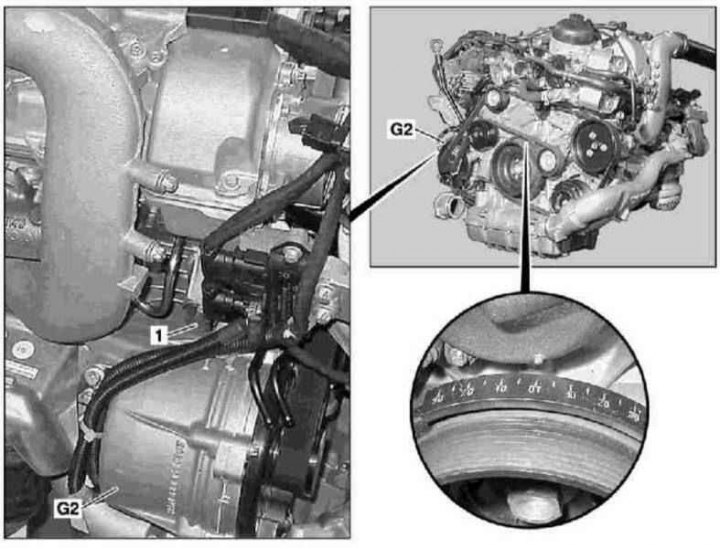
628 Series Timing Chain Tensioner Installation Details
1. Installation details of the 628 series timing chain tensioner are shown in the illustration, to which all references in the text refer.
2. Remove generator (G2) (see chapter Engine Electrical Systems).
3. Remove chain tensioner (1).
4. Installation is carried out in the reverse order - do not forget to replace the sealing element.
Tension bar
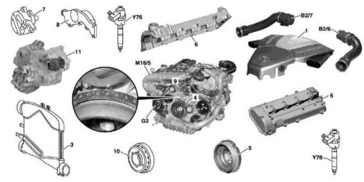
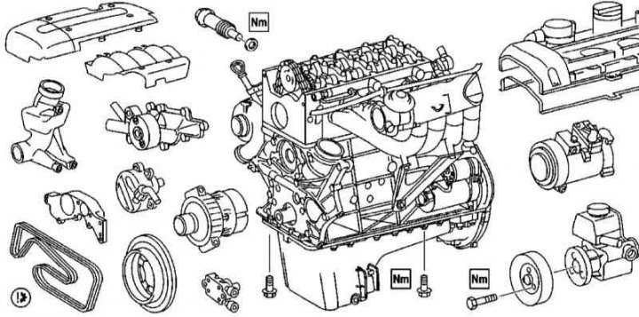
Preparing to remove the tensioner bar from the 628 series engine
1 - Air cleaner; 3 - Cooler of the air pressurization path; 4 - Auxiliary drive belt; 5 - Vibration damper / drive belt pulley; 6 - Cylinder head covers; 7 - Vacuum pump; 8 - Front cover; 9 - Cover; 10 - Centrifuge; 11 - injection pump; В2/6 - Left MAF sensor; В2/7 - Right MAF sensor; M16 / 5 - Throttle actuator; G2 - Generator; Y76 - Nozzle
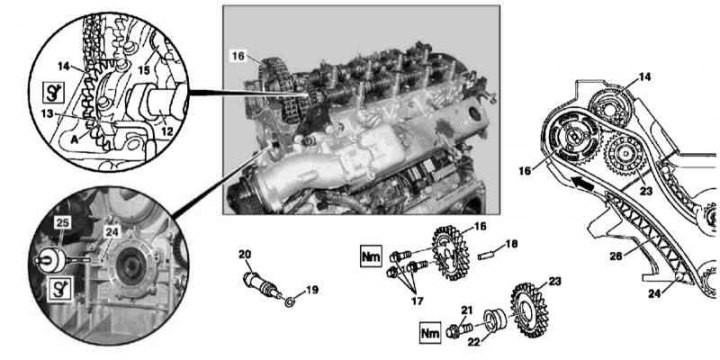
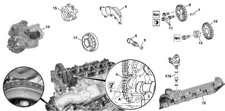
Tension bar installation details on 628 series engine
12 - Intake camshaft; 13 - Locking rod; 14 - Camshaft gear; 15 - Final camshaft; 16 - Camshaft sprocket; 17 - Bolt; 18 - Guide pin; 19 - Sealing element; 20 - Chain tensioner; 21 - Bolt; 22 - Bushing; 23 - Intermediate sprocket of injection pump; 24 - Guide pins; 25 - Impact extractor; 26 - Tension bar; A - Hole
1. Illustrative preparation for removal and installation details of the tensioner bar on the 612 series engine are shown in the illustrations, to which all references in the text refer.
2. Remove the air distributor.
3. Disconnect and take aside the right sleeve of an inlet path of pressurization of air.
4. Remove the left front wheel arch protection locker.
5. Disconnect and take aside the left sleeve of an inlet path of pressurization of air.
6. Remove the left and right nozzle covers.
7. Remove nozzles (Y76) (see chapter Removal and installation of the fuel distributive highway and nozzles).
8. Remove cylinder head covers (6).
9. Remove the bypass air sleeve.
10. Remove the accessory drive belt (4).
11. Remove vibration damper/drive belt pulley (5).
12. Remove the vacuum pump (7).
13. Remove injection pump (11).
14. Remove front cover (8) cylinder heads (see Section Removing and installing timing covers).
15. Remove the generator (G2) (see chapter Engine Electrical Systems).
16. Block the intake camshafts (12) both cylinder heads.
17. Mark the position of the chain on the camshaft sprocket (16).
18. Remove chain tensioner (20) (see above).
19. Screw off the asterisk (16) and remove it from the exhaust camshaft stub (15).
20. Remove the injection pump intermediate sprocket (23) complete with cylindrical insert (22).
21. Using a percussion extractor (25) knock out guide pins (24).
22. Pulling up and out, remove the tension bar (26).
23. Installation is carried out in the reverse order.
24. Finally, start the engine and check for signs of leak development. Also clear the OBD memory (see chapter Engine Electrical Systems).