
Checking the basic position of the 612 engine camshafts
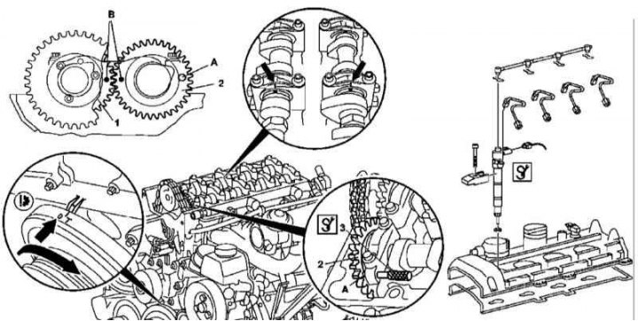
1. Illustrative material for checking the basic position of the 612 engine camshafts is presented in the illustration, which includes all references in the text.
2. Remove nozzles (Y76) (see chapter Removal and installation of the fuel distributive highway and nozzles).
3. Remove the cylinder head cover.
4. Having turned the crankshaft in the normal direction, bring the piston of the first cylinder to the TDC position, the marks of the camshaft and its bearing caps must be aligned.
5. Block the camshafts with a special rod (3), threaded through the hole in the cover of the first shaft bearing and tucked into the hole (A) in gear (2) intake camshaft.
6. With the correct basic label setting (IN) camshaft gears (1 and 2) should be combined. In addition, the marks applied to the shaft bodies and their bearing caps must be aligned (arrows).
7. If necessary, remove the camshafts (see Section Removal and installation of timing components) and install them in place, ensuring the correct alignment of the marks.
8. Reinstall the removed components in reverse order of removal.
M628
Setting the basic position of the camshafts of the 628 series engine
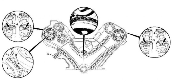
1 - Intake camshaft gear; 2 - Gear wheel of a final camshaft; 3 - Intake camshaft; 4 - Final camshaft; 5 - Chain tensioner; B - Setting marks
1. Illustrative material for adjusting the basic position of the camshafts of the 628 series engine is presented in the illustration, which includes all references in the text.
2. Remove the cylinder head covers.
3. Turning the crankshaft in the normal direction, bring the piston of the first cylinder to the TDC position.
4. Check the basic position of the camshafts - the gears must be turned with marks (IN) to each other, in addition, the marks applied to the bodies of the shafts and the covers of their bearings must be aligned (arrows).
5. If necessary, make the appropriate adjustment.
6. Reinstall the removed components in reverse order of removal.