
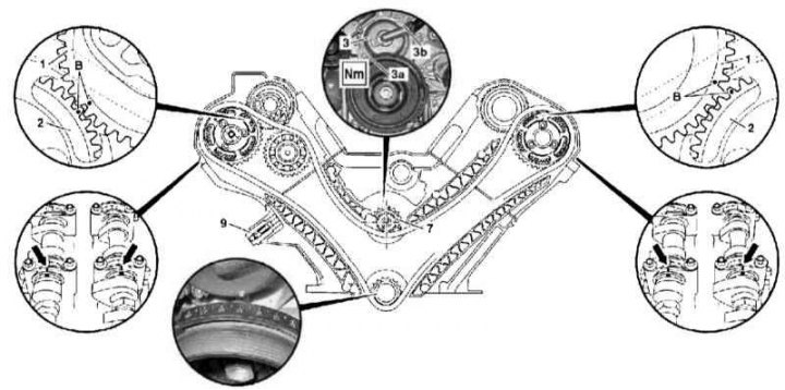
Checking the basic position of the balance shaft of the 628 engine
1 - Intake camshaft gear; 2 - Gear wheel of a final camshaft; 3 - Cover; 3a - Lower bolt; 3b - Top bolt; 5 - Spring; 7 - Asterisk of a balancing shaft; 9 - Setting marks
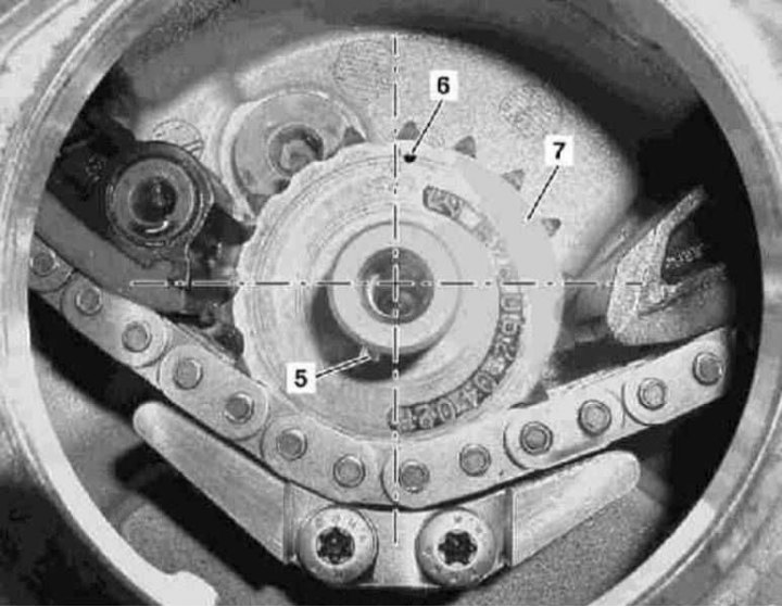
Checking the basic position of the balance shaft of the 628 engine
5 - Spring; 6 - Marking; 7 - Balance shaft sprocket
1. Illustrative material for checking the basic position of the balancing shaft on 628 series engines is presented in illustrations, which include all references in the text.
2. Remove the cylinder head covers.
3. Remove the electric cooling fan assembly (see chapter Cooling, heating and air conditioning systems).
4. Remove the bottom bolt (3a) lids (3), - Turn the crankshaft in the normal direction to gain access to the bolt.
5. Bring the piston of the first cylinder to the TDC position.
6. Turn out the top bolt (3b) and remove the cover (3).
7. Remove the centrifuge.
8. Make sure the tensioner (9) provides the required tension force of the gas distribution chain.
9. Install the cover on the crankcase (3) and secure it with the top bolt (3b).
10. Turn the crankshaft two full turns in the normal direction, again bringing the piston of the first cylinder to the TDC position.
11. Remove the cover again (3).
12. Make sure the basic setting of the camshafts is correct (see Section Setting the basic position of the camshafts).
13. Check the correctness of the basic setting of the balancing shaft, the spring (5) which should occupy the position shown in the picture, and the marking (6) on an asterisk (7) be slightly out of position «at 12 o'clock».
14. Acting in the reverse order of dismantling, install the removed components in their places.