
Preparing to remove the cylinder head of the 612 series engine
Preparing to remove the cylinder head of the 612 series engine
Removing the cylinder head of the 612 series engine
1. Illustrative material for removing and installing the cylinder head of the 612 series engine is presented in illustrations, which include all references in the text.
2. Open the hood and lock it in an upright position.
3. Disconnect the negative cable from the battery.
4. Remove the bottom section of the soundproofing.
5. Empty the cooling system (see chapter Checking the cooling system and frost resistance of the coolant, changing the fluid).
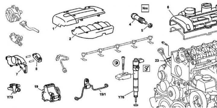
6. Remove the cylinder head cover trim panels (1 and 2).
7. Remove the air cleaner (see chapter Servicing Air Inlet Components).
8. Disconnect hoses of a cooling path from the thermostat.
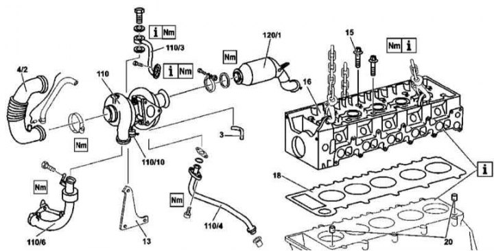
9. Disconnect the inlet sleeve (4/2) from the turbocharger (110).
10. Disconnect the vacuum hose (3) vacuum block (110/10) turbocharger (110).
11. Remove the expansion tank of the cooling system (see chapter Cooling, heating and air conditioning systems) and, without disconnecting the hoses, move it to the side.
12. Remove nozzles (Y76).
13. Remove the cylinder head cover (6).
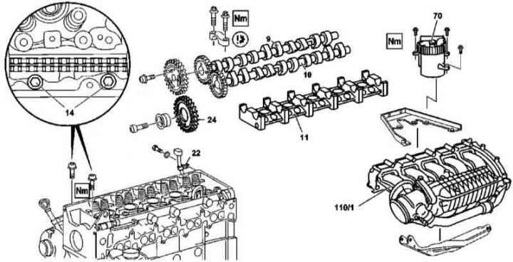
14. Turning the crankshaft in the normal direction, bring the engine to the TDC position of the piston of the first cylinder, the marks on the bodies of the camshafts and bearing caps must be aligned (arrows).
15. Using a special tool, block the flywheel ring gear.
16. Remove chain tensioner (4) (see Section Removal and installation of timing drive components).
17. Remove front cover (7) cylinder heads (see Section Removing and installing timing covers).
18. Remove the top chain guide (8) (see Section Removal and installation of timing drive components).
19. Remove camshafts (9 and 10) (see Section Removal and installation of timing components).
20. Remove the bed of camshafts (11).
21. Remove intermediate sprocket (24).
22. Disconnect pressure line (19/1) from injection pump (19).
23. Remove the return line laid between the injection pump and the fuel line.
24. Remove injection pump (19).
25. Disunite contact sockets of an electroconducting on a head of cylinders.
26. Remove the main fuel filter (70).
27. Remove the air distribution sleeve (110/1).
28. Unbolt the guide tube brackets from the cylinder head (22 and 23).
29. Disconnect primary catalytic converter (120/1) from the turbocharger (110).
30. Disconnect from the turbocharger (11) air sleeve (110/6) and oil return pipe (110/4).
31. Remove the bolts (14) attaching the cylinder head to the timing cover.
32. Loosen the bolts in several steps (15) head mounting.
33. Remove the bolts (15) and check their status.
34. Thoroughly clean the mating surfaces of the cylinder head and block and the threaded holes in the block.
35. Installation is carried out in the reverse order - a new seal (18) is laid on the surface of the block mating with the head. Make sure the guide bushings are installed correctly (20).
36. Finally, start the engine and check for signs of leaks. Also clear the memory of the on-board self-diagnosis module (see chapter Engine Electrical Systems).
M628
Preparing to remove the left cylinder head of the 628 series engine
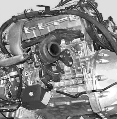
1 - Contact connector for electrical wiring; 2 - Turbocharger oil return pipe; 3 - Turbocharger support bracket

Preparing to remove the left cylinder head of the 628 series engine
4 - Bearing pins of the chain guides; 5 - Chain guides
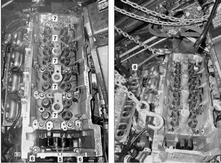
Removal of the left cylinder head of the 628 series engine
5 - Chain guides; 6 - Bolts; 7 - Head mounting bolts; 8 - Lifting rigging
1. Illustrative material for removing and installing cylinder heads (on the example of the left) of the 628 series engine is shown in the illustrations, to which all references in the text refer.
2. Remove the EGR cooler.
3. Remove cylinder head covers.
4. Remove chain tensioner (see Section Removal and installation of timing drive components).
Right head
1. Remove the air inlet sleeve.
2. Remove the lower sleeve of a way of a pressurization of air.
3. Remove the injection pump intermediate sprocket (see Section Removal and installation of timing drive components).
4. Remove the bed of camshafts (see Section Removal and installation of timing components).
5. Release fasteners and pull back the right three-function catalytic converter (TWC).
6. Disconnect the electrical wiring from the right turbocharger (1).
7. Disconnect the oil return pipe from the right turbocharger (2), - the sealing elements of the tube must be replaced without fail.
8. Remove the support bracket (3) right turbocharger.
Left head
1. Follow the procedures in the previous order of execution, adjusting for the binding of components to your head.
2. Remove the oil filter cover.
3. Mark position of a gas-distributing chain on an asterisk of a drive of camshafts.
4. Remove the drive sprocket from the exhaust camshaft stub.
5. Using a suitable extractor, remove the chain guide pins (4).
6. Tie up the guides (5) one to another.
Both heads
1. Disconnect the electrical wiring from the glow plugs.
2. Remove the bolts (6) head mounting.
3. Loosen then remove the bolts in several steps (7) head mounting.
4. Check the condition of the bolts (7), replace them if necessary.
5. Connect the lifting chains (8) and using a winch, remove the head from the cylinder block.
6. Thoroughly clean the mating surfaces of the cylinder head and block and the threaded holes in the block.
7. Install in reverse order - new gasket (18) is laid on the surface of the block mating with the head. Make sure the guide bushings are installed correctly (20).
8. Finally, start the engine and check for signs of leaks. Also clear the memory of the on-board self-diagnosis module (see chapter Engine Electrical Systems).