
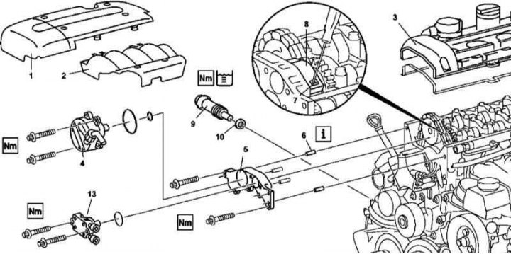
612 Series Engine Front Cylinder Head Cover Installation Details
1. Details of the installation of the front cover of the cylinder head of the 612 series engine are shown in the illustration, to which all references in the text refer.
2. Remove the cylinder head (3) (see Section Removing and installing the head (OK) cylinders).
3. Remove chain tensioner (9) (see Section Removal and installation of timing drive components).
4. Remove the pre-fuel pump (13) (see chapter Removal and installation of the preliminary fuel pump).
5. Turn out screws of fastening of a forward cover of a head of cylinders (5).
6. Using a screwdriver, pry up the ratchet (7) upper chain guide lock (8).
Note. The guide will remain in the timing case.
7. Pulling forward, remove the front cylinder head cover (5), - be careful not to drop the guide pins.
8. Before installation carefully clean mating surfaces of a forward cover and a head of cylinders.
9. Apply sealant to the mating surface of the cover.
10. Installation is carried out in the reverse order. Make sure all fasteners are tightened to the correct torque.
11. Finally, start the engine and check for signs of leaks.
M628
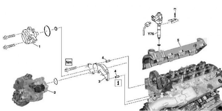
628 Series Front Cylinder Head Cover Installation Details
1. Details of the installation of the front cover of the cylinder head of the 628 series are shown in the illustration, to which all references in the text refer.
2. Air distribution sleeve.
3. Release and take aside an inlet tube of an air pressurization path.
4. Remove nozzles (Y76) right bank of cylinders.
5. Remove the cover (5) right cylinder head.
6. Remove the bypass sleeve of the air boost path.
7. Disconnect from engine block (above the generator) Glow plug wiring support bracket.
8. Remove the vacuum pump (1)
9. Remove the high pressure fuel pump (injection pump) (2).
10. Remove the fixing screws and pull forward to remove the front cover (3).
11. Before installation carefully clean mating surfaces of a forward cover and a head of cylinders.
12. Apply sealant to the mating surface of the cover.
13. Installation is carried out in the reverse order.
14. Track, that all fixture has been tightened with demanded effort.
15. Finally, start the engine and check for signs of leaks.
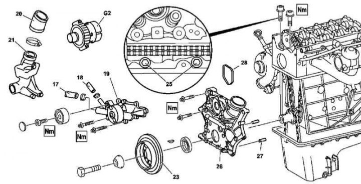
Timing cover (612 series motors only)
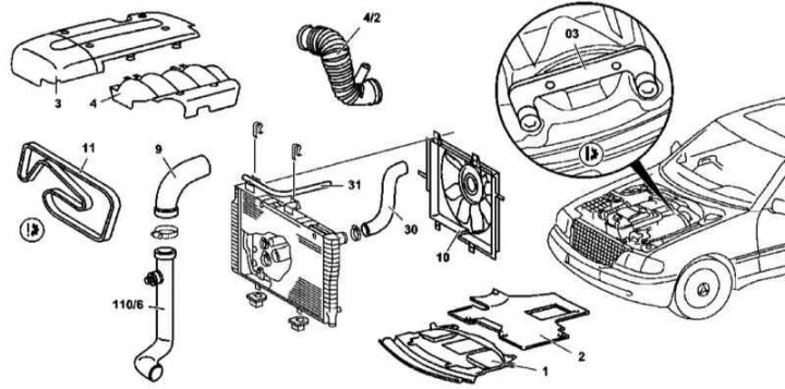
Timing cover installation details on 612 series engines
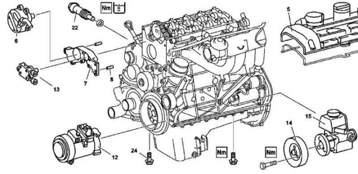
Timing cover installation details on 612 series engines
Timing cover installation details on 612 series engines
1. The details of installing the timing cover on the 612 series engine are shown in the illustrations, which include all references in the text.
2. Open the hood and lock it in an upright position.
3. Disconnect the negative cable from the battery.
4. Remove the bottom section of the soundproofing.
5. Empty the cooling system (see chapter Checking the cooling system and frost resistance of the coolant, changing the fluid).
6. Drain the engine oil (see chapter Changing the engine oil and oil filter).
7. Remove the cylinder head cover trim panels (3 and 4).
8. Disconnect the coolant hoses (30 and 31).
9. Remove the air intake sleeve (4/2).
10. Remove air intake hose (110/6) complete with hose connected to it (9).
11. Remove the electric cooling fan (10).
12. Remove nozzles (Y76) (see chapter Removal and installation of the fuel distributive highway and nozzles).
13. Remove the cylinder head cover (5).
14. Having turned the crankshaft in the normal direction, bring the piston of the first cylinder to the TDC position, the marks of the camshaft and its bearing caps must be aligned.
15. Using a special tool (03) lock the flywheel/drive plate ring gear.
16. Remove chain tensioner (22) (see Section Removal and installation of timing drive components).
17. Release the guide on the bracket.
18. Remove the thermostat (see chapter Cooling, heating and air conditioning systems).
19. Remove front cover (7) cylinder heads (see above).
20. Remove the accessory drive belt (see chapter Engine).
21. Disconnect the electrical wiring from the A/C compressor (12).
22. Screw off the compressor (12) and, without disconnecting the refrigeration lines, take it aside.
23. Disconnect the lines of the cooling path connected to the liquid heat exchanger of the lubrication system (see Section Maintenance of the lubrication system).
24. Disconnect the hoses (17 and 18) from the water pump (19).
25. Remove the water pump (19) (see chapter Cooling, heating and air conditioning systems).
26. Take off the sleeve (21) air intake path.
27. Remove the bolts (24) fastenings of the oil pan on the side of the timing cover, only loosen the other bolts of the oil pan.
28. Remove the M8 bolts (25) fastening the timing cover to the cylinder head.
29. Remove the timing cover.
30. If the timing chain is to be replaced, remove the accessory drive belt tensioner.
31. If the cover is to be replaced, remove the liquid heat exchanger of the lubrication system.
32. Thoroughly clean the mating surfaces.
33. Apply sealant to the mating surface of the cover.
34. Installation is in reverse order - do not forget to reinstall the guide pins.
35. Finally, check the engine for signs of developing fluid leaks (oil, fuel, coolant, A/C coolant, etc.). Also clear the memory of the on-board self-diagnosis module (see chapter Engine Electrical Systems).