

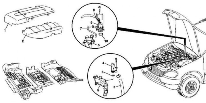
Installation details of the liquid oil filter heat exchanger on the 612 series engine
10 - Sealing element; 70 - Main fuel filter
1. The installation details of the oil filter liquid heat exchanger on the 612 series engine are shown in the illustration, to which all references in the text refer.
2. Open the hood and lock it in an upright position.
3. Remove trim panels (1 and 2).
4. Remove the cover (3) oil filter housing, remove the filter element and drain the oil into a prepared container.
5. Remove the bottom section of the soundproofing.
6. Empty the cooling system (see chapter Checking the cooling system and frost resistance of the coolant, changing the fluid).
7. Disconnect from the EGR heat exchanger (11) coolant hose (12).
8. Remove the fuel cooler.
9. Turn out bolts of fastening of the heat exchanger EGR (11) to the cylinder head.
10. Separate the EGR heat exchanger from the air distribution pipeline (110/1).
11. Remove the pipeline (110/1).
12. Remove the fuel line (21) (see chapter Removal and installation of the fuel distributive highway and nozzles).
13. Disconnect the coolant hose (7) from liquid cooler (8).
14. Disconnect ATF lines (9) from the heat exchanger (8), - get ready to collect the escaping fluid.
15. Disconnect the heat exchanger (8) from the timing cover.
16. Installation is carried out in the reverse order.
17. Check the coolant level, make appropriate adjustments if necessary (see chapter Checking the cooling system and frost resistance of the coolant, changing the fluid).
18. Finally, start the engine and check for signs of leak development.
19. After warming up the engine to normal operating temperature, turn it off and, after about 2 minutes, check the level of impellent oil. Make appropriate adjustments if necessary (see chapter Changing the engine oil and oil filter).
Removal and installation of the oil pan
Preparing to Remove the 612 Series Engine Sump
10 - Sealing element; 8 - Outlet fuel line
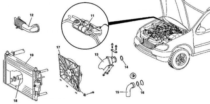
Preparing to Remove the 612 Series Engine Sump
11 - Expansion tank of the cooling system; 12 - Air intake; 13 - Connected to the turbocharger, the sleeve of the air pressurization path; 14 - O-ring; 15 - Connected to the mixing chamber, the sleeve of the air pressurization path; 16 - O-ring; 17 - Electric fan of the cooling system; 18 - Hose of the cooling path; 19 - Radiator
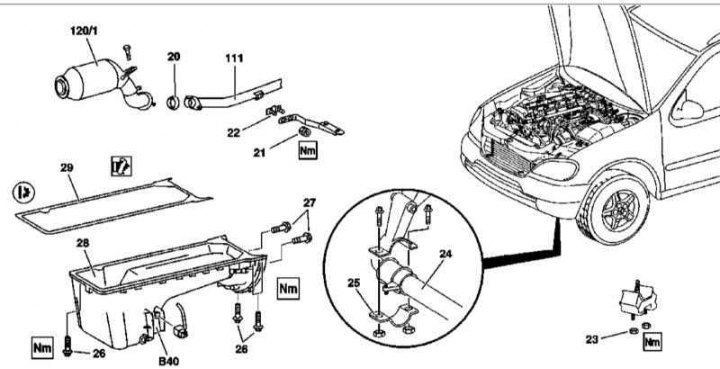
612 Series Engine Sump Installation Details
20 - Expansion tank of the cooling system; 21 - Self-locking nut; 22 - Threaded plate; 23 - Nut for fastening the suspension support of the power unit to the vehicle frame; 24 - Torsion bar; 25 - Clamp; 26 - Pallet fixing bolt; 27 - Bolt of fastening of the pallet; 28 - Oil pan; 29 - Sealing gasket; 111 - TWC; 120/1 - Primary catalytic converter; B40 - Oil level sensor
1. Details of the installation of the oil pan on the 612 series engine are shown in the illustrations, which include all references in the text.
2. Open the hood and lock it in an upright position.
3. Disconnect the negative cable from the battery.
4. Remove the bottom section of the soundproofing.
5. Drain the engine oil (see chapter Changing the engine oil and oil filter).
6. Empty the cooling system (see chapter Checking the cooling system and frost resistance of the coolant, changing the fluid).
7. Remove trim panels (1 and 2).
8. Disconnect the coolant hose (3) from connector (4).
9. Disconnect the hose (3) from EGR (5).
10. Disconnect the fuel hose (7) from fuel preheater (9).
11. Remove the device (9) with EGR (5), - prepare a new gasket.
12. Remove the expansion tank of the cooling system (11) (see chapter Cooling, heating and air conditioning systems).
13. Remove the air intake (12).
14. Remove the air sleeve (13), - prepare a new O-ring (6).
15. Disconnect the air hose (15) from the mixing chamber.
16. Remove the cooling fan (17).
17. Disconnect the hose (18) from the radiator (19).
18. Disconnect the electrical wiring from the engine oil level sensor (B40).
19. Release the primary catalytic converter fastening clamp (120/1) to TWC (111).
20. Remove the torsion bar clamps (24).
21. Give nuts (23) front suspension mounts of the power unit.
22. Hang the engine on the winch.
23. Loosen the mounting bolts (26 and 27) and drain the oil from the oil pan (28).
24. Finally turn out bolts and remove the pallet.
25. Remove the gasket (29).
26. Thoroughly clean the mating surfaces of the pallet and block.
27. Installation is carried out in the reverse order. Remember that all sealing elements must be replaced without fail. Make sure all fasteners are tightened to the correct torque.
28. Finally, start the engine and check for signs of leaks. Also clear the OBD memory (see chapter Engine Electrical Systems).
Removal and installation of the oil level sensor
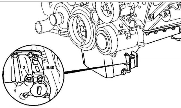
612 Series Engine Oil Level Sensor Installation Details
1 - Oil pan; 2 - Drain plug; B40 - Oil level sensor
1. The installation details of the 612 series engine oil level sensor are shown in the illustration, to which all references in the text refer.
2. Open the hood and lock it in an upright position.
3. Remove the bottom section of the soundproofing.
4. Drain the engine oil (see chapter Changing the engine oil and oil filter).
5. Disconnect the electrical wiring and remove the oil level sensor (B40).
6. Installation is carried out in the reverse order.
7. Start the engine and check it for signs of leak development.
Removal and installation of oil sprayers
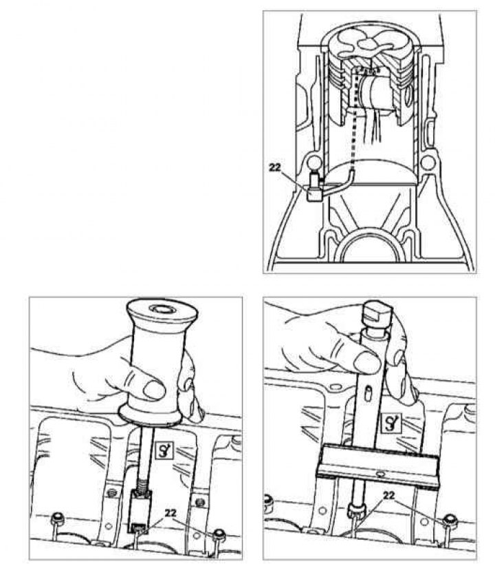
Details of installing oil sprayers on a 612 series engine
Note. Maintenance of oil sprayers is associated with the dismantling of the crankshaft and its implementation should be entrusted to car service specialists.
1. Details of installing oil sprayers on a 612 series engine are shown in the illustration, to which all references in the text refer.
2. Remove the oil pan (see above).
3. Remove the crankshaft.
4. Remove oil nozzles (22).
5. Installation is carried out in the reverse order.
Removal and installation of the oil pump
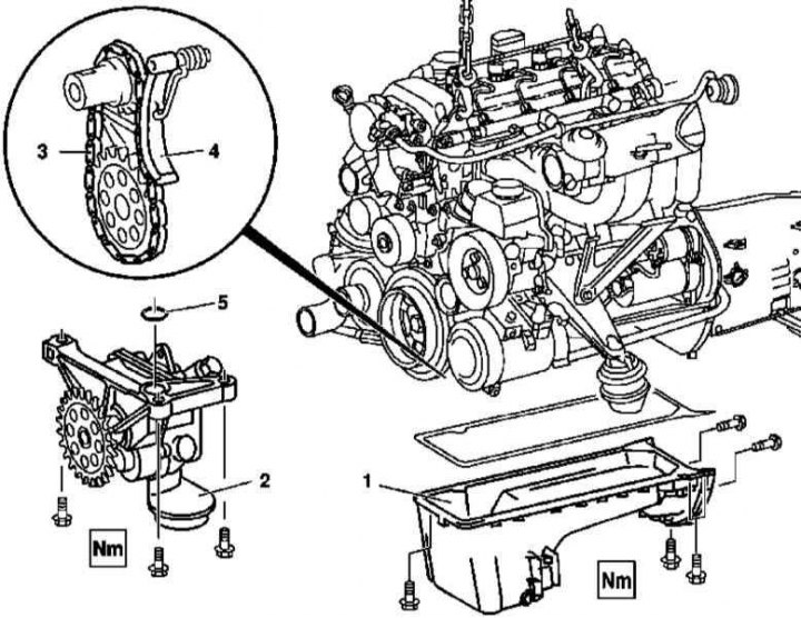
612 Series Engine Oil Pump Installation Details
1 - Oil pan; 2 - Oil pump; 3 - Oil pump drive chain; 4 - Chain tensioner; 5 - O-ring
1. Details of the installation of the oil pump of the 612 series engine are shown in the illustration, to which all references in the text refer.
2. Remove the oil pan (1) (see above).
3. Turn out bolts of fastening of the oil pump (2) to the engine crankcase.
4. Press the tensioner (4) and drop the chain (3) from the pump drive sprocket. Remove pump assembly (2).
5. Thoroughly clean the mating surfaces of the pump and motor block.
6. Fill pump assembly with fresh oil.
7. Installation is carried out in the reverse order - do not forget to clean the oil intake strainer.
Replacing the oil pump drive chain
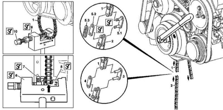
Details of installing the oil pump drive chain on the 612 series engine
1. Details of the installation of the oil pump drive chain on the 612 series engine are shown in the illustration, to which all references in the text refer.
2. Remove the oil pan (see above).
3. Remove the oil pump (see above).
4. Using a special tool, dismember the pump drive chain and remove it from the engine.
5. Installation is carried out in the reverse order - use a special tool to articulate the chain.
628 series engine
Removal and installation of an oil filter casing
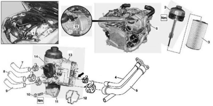
628 Series Engine Oil Filter Installation Details
1 - Air intake; 2 - Cover; 3 - Filter element; 4 - Line of the cooling path; 5 - Ventilation line; 6 - Left inlet sleeve of the air pressurization path; 7 - Line of the cooling path; 8 - Ventilation line; 9 - Line of the cooling path; 10 - Bolt; 11 - Oil filter casing; 12 - Sealing gasket; 13 - Liquid heat exchanger; 14 - Crankcase ventilation valve (PCV); 15 - Support bracket
1. Details of installing an oil filter on 628 series engines are shown in the illustration, to which all references in the text refer.
2. Remove the bottom section of the soundproofing.
3. Empty the cooling system (see chapter Checking the cooling system and frost resistance of the coolant, changing the fluid).
4. Lift the power package cover.
5. Remove the electric cooling fan.
6. Unscrew the cover (2) oil filter housing (11).
7. Remove a hose of a cooling path going from a radiator to the thermostat.
8. Disconnect from filter housing (11) cooling lines (4) and ventilation (5) paths, release them from the support bracket (arrow).
9. Also disconnect from the line filter (7, 9 and 8).
10. Remove the support bracket (15).
11. Turn out bolts (10).
12. Remove the oil filter cover (11)
13. Installation is carried out in the reverse order.
14. Finally, start the engine and check the filter for signs of leaks.
15. Check engine oil level, correct if necessary (see chapter Changing the engine oil and oil filter).
Removal and installation of the liquid heat exchanger of the oil filter
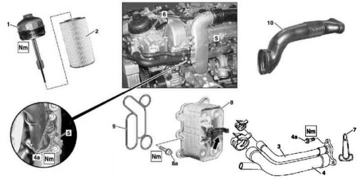
Installation details of the liquid oil filter heat exchanger on the 628 series engine
1 - Cover; 2 - Filter element; 3 - Line of the cooling path; 4 - Ventilation line; 4a - Bolt; 5 - Left inlet sleeve of the air pressurization path; 6 - Oil filter casing; 7 - Sealing gasket; 8 - Liquid heat exchanger; 8a - Bolt; 9 - Sealing gasket; 10 - Air intake
1. Installation details of the oil filter liquid heat exchanger on the 628 series engine are shown in the illustration, to which all references in the text refer.
2. Open the hood.
3. Lift the power package cover.
4. Unscrew the cover (1) oil filter housing (6) and remove the filter element (2).
5. Remove the left front wheel and wheel arch protection locker.
6. Remove the bottom section of the soundproofing.
7. Empty the cooling system (see chapter Checking the cooling system and frost resistance of the coolant, changing the fluid).
8. Disconnect from the oil filter housing (6) cooling lines (3) and ventilation (4) paths.
9. Remove from the oil filter housing (6) liquid heat exchanger (8).
10. Thoroughly clean the mating surfaces, prepare a new seal (9).
11. Installation is carried out in the reverse order.
12. Finally, start the engine and check for signs of leaks.
13. Check engine oil level, correct if necessary (see chapter Changing the engine oil and oil filter).
Removal and installation of the oil pan
Bottom section of pallet
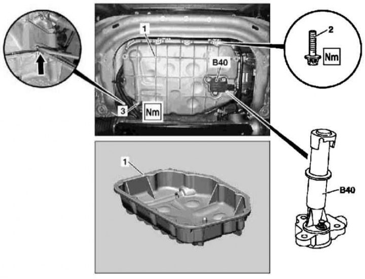
628 Series Lower Sump Installation Details
1 - The lower section of the oil pan; 2 - Bolt TORX M8xM6x20; 3 - Drain plug of the pallet; B40 - Engine oil level sensor
1. The installation details of the lower section of the oil pan on the 628 series engine are shown in the illustration, to which all references in the text refer.
2. Remove the bottom section of the soundproofing.
3. Disconnect the electrical wiring from the oil level sensor (B40).
4. Drain the engine oil (see chapter Changing the engine oil and oil filter).
5. Remove/Lower Front Axle Assembly (see chapter Suspension and steering).
6. Turn out bolts of fastening of a basic arm of the bottom sleeve of a way of supercharging of air on the right wall of the lower section of the pallet crankcase.
7. Turn out fixing bolts (2) and remove the bottom section of the pallet (1), if necessary, prying it in the place indicated by the arrow.
8. Remove the oil level sensor (B40).
9. Thoroughly clean the mating surfaces of the bottom and top sections of the pallet.
10. Installation is carried out in the reverse order - make sure that the sealant is applied correctly to the mating surface of the bottom section of the pallet.
Upper pallet section
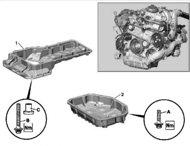
628 Series Top Sump Installation Details
1 - Upper section of the pallet; 2 - Lower section of the pallet; A - Bolt TORX M6x20; B - Bolt TORX M6x40; C - Sleeve
1. Details of installation of the upper section of the oil pan on the 628 series engine are shown in the illustration, to which all references in the text refer.
2. Remove the lower section of the oil pan (2) (see above).
3. Remove the top section of the pallet (1).
4. Thoroughly clean the mating surfaces.
5. Installation is carried out in the reverse order - follow the correct application of the sealant.
Removal and installation of the oil pump
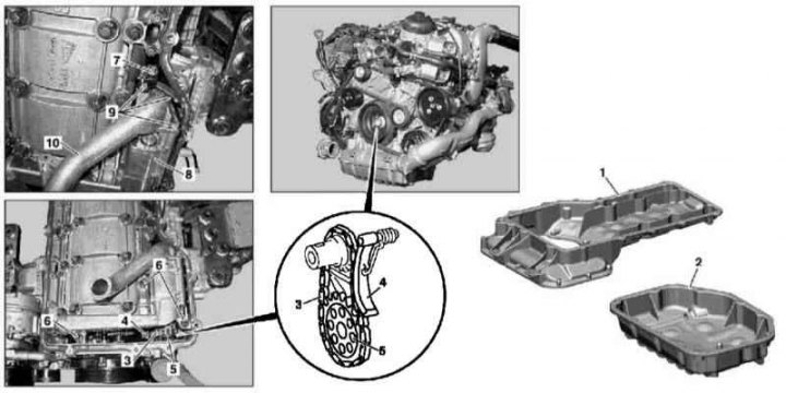
Details of installing an oil pump on a 628 series engine
1 - Upper section of the oil pan; 2 - Lower section of the oil pan; 3 - Oil pump drive chain; 4 - Chain tensioner; 5 - Pump drive sprocket; 6 - Bolt; 7 - Bolt; 8 - Oil pump; 9 - Bolt; 10 - Cover with oil line
1. Details of the installation of the oil pump of the 628 series engine are shown in the illustration, to which all references in the text refer.
2. Remove both sections of the oil pan (see above).
3. Remove the screw (7).
4. Turn out bolts (6) oil pump mounts (8).
5. Pull back the tensioner (4) drive chain (3) from an asterisk (5) pump drive (8). If necessary, remove the chain and replace it.
6. Remove the pump assembly (8).
7. Turn out bolts (9) and disconnect the cover with the oil line from the pump (10).
8. Clean the oil pickup strainer.
9. Thoroughly clean mating surfaces.
10. Fill pump assembly with fresh oil.
11. Installation is carried out in the reverse order.