
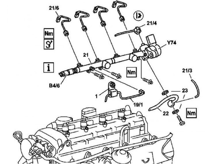
Details of installation of the fuel distributive highway on models 163.113 (612 series engine)
1 - Pressure line support bracket; 19/1 - High pressure pump pressure line; 21 - Fuel line; 21/3 - Oil drain line; 21/4 - Fuel return line; 21/6 - Fuel lines for injectors; 22 - Fuel return line from the cooler; 23 - O-rings; B4 / 6 - Fuel line pressure sensor; Y74 - Pressure control valve
1. Details of installation of the fuel distributive highway on models 163.113 (612 series engine) shown in the illustration, which includes all references in the text.
2. Remove panels of finishing of a cover of a head of cylinders.
3. Disconnect wiring from sensor (В4/6) and pressure control valve (Y74).
4. Remove fuel injector lines (21/6).
5. Remove from fuel line (21) pressure (19/1) and return (21/4) lines.
6. Remove fuel return line from cooler (22) and oil return line (21/3).
7. Remove the fuel line, if necessary, remove the nozzles (see below).
8. Installation is carried out in the reverse order - do not forget to replace all sealing elements.
9. Finally, start the engine and check the fuel path components for signs of leak development, clear the memory of the on-board self-diagnosis module (see chapter Engine Electrical Systems).
Nozzles
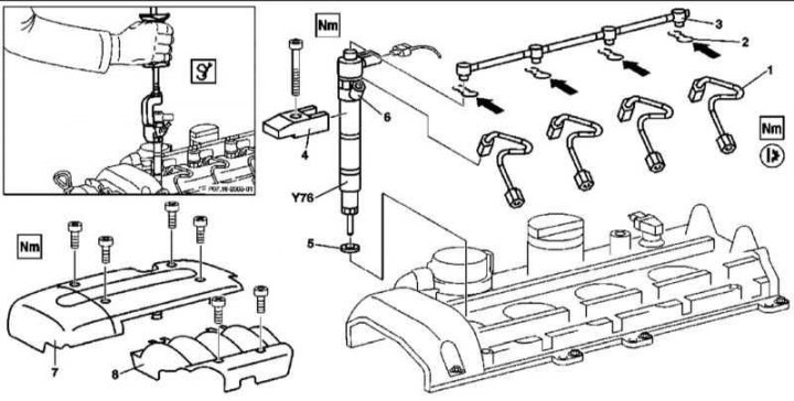
Details of installation of nozzles on models 163.113 (612 series engine)
1. Details of installation of nozzles on models 163.113 (612 series engine) shown in the illustration, which includes all references in the text.
2. Remove the expansion tank of the cooling system.
3. Remove the cylinder head cover trim panels (7 and 8).
4. Disconnect from injectors (Y76) wiring.
5. Release the latches (2) and remove the oil return line (3).
6. Remove the clips (4) and remove the injectors (Y76).
7. Installation is carried out in the reverse order - do not forget to replace the sealing elements.
8. Finally, start the engine and check the fuel path components for signs of leak development, clear the memory of the on-board self-diagnosis module (see chapter Engine Electrical Systems).
Models 163.128
Highway
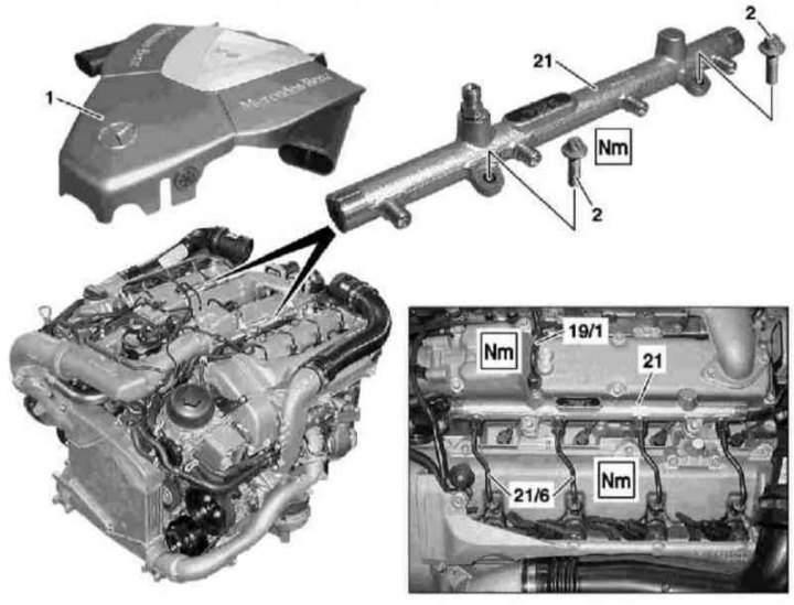
Details of installation of the fuel distributive highway on models 163.128 (628 series engine)
1 - Air cleaner; 2 - Bolts; 19/1 - Pressure line valve block / fuel line; 21 - Fuel line; 21/6 - Fuel lines for injectors
1. Details of installation of the fuel distributive highway on models 163.128 (628 series engine) shown in the illustration, which includes all references in the text.
2. Remove the air distributor (see Section Servicing Air Inlet Components).
3. Remove fuel injector lines (21/6) and pressure fuel line (19/1).
4. Turn out bolts (2) and remove the fuel line (21).
5. Installation is carried out in the reverse order - tighten the fixing bolts only after installing the pressure lines.
6. Finally, start the engine and check the fuel path components for signs of leaks, clear the memory of the on-board self-diagnosis module (see chapter Engine Electrical Systems).
Nozzles
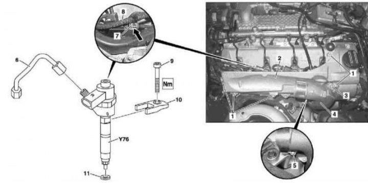
Details of installation of nozzles on models 163.128 (628 series engine)
1 - Screws; 2 - Cover; 3 - Screw; 4 - Inlet air duct of the boost path; 5 - Screw; 6 - Fuel injector line; 7 - Retainer; 8 - Oil drain line; 9 - Screw; 10 - Retainer; 11 - O-ring; Y76 - Nozzle
1. Details of installation of nozzles on models 163.128 (628 series engine) shown in the illustration, which includes all references in the text.
2. Remove the air distributor (see Section Servicing Air Inlet Components).
3. Remove the left air duct (4).
4. Remove the left front wheel and wheel arch protection locker.
5. Disconnect an inlet air line from a cover of a head of cylinders and take away it aside.
6. Remove the right and left nozzle covers (2).
7. Disconnect the wiring and fuel lines from the injectors (6).
8. Release the latches (7), then remove and lay aside the oil return line (8).
Attention! The fasteners must be replaced without fail!
9. Remove the clips (10) and remove the injectors (Y76).
10. Installation is carried out in the reverse order - do not forget to replace the sealing elements.
11. Finally, start the engine and check the fuel path components for signs of leak development, clear the memory of the on-board self-diagnosis module (see chapter Engine Electrical Systems).