



Models 463.323 (M612)
Highway
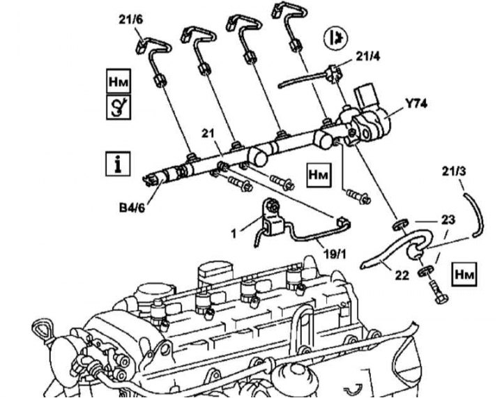
Fuel Distribution Line Installation Details (M612)
1 - Pressure line support bracket; 19/1 - Pressure line of high-pressure fuel pump; 21 - Fuel line; 21/3 - Oil drain line; 21/4 - Fuel return line; 21/6 - Fuel lines of injectors; 22 - Fuel return line from cooler; 23 - Sealing rings; B4/6 - Fuel line pressure sensor; Y74 - Pressure Regulator Valve
1. Remove the cylinder head cover trim panels.
2. Disconnect the electrical wiring from the sensor (B4/6) and the pressure regulating valve (Y74).
3. Remove the fuel injector lines (21/6).
4. Disconnect the pressure (19/1) and return (21/4) lines from the fuel line (21) - use a second wrench to hold the union nut from turning.
5. Remove the fuel return line from the cooler (22) and the oil return line (21/3), - have replacement sealing rings ready.
6. Remove the fuel line (21), if necessary remove the injectors (see below).
7. Installation is carried out in the reverse order - do not forget to replace the sealing elements.
8. Finally, start the engine and check the fuel system components for signs of developing leaks, clear the memory of the on-board diagnostic module (see Chapter Engine electrical systems).
Nozzles
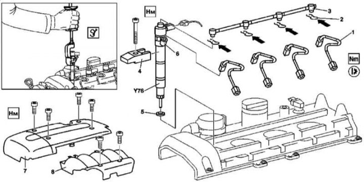
Injector installation details (M612)
1. Remove the cylinder head cover trim panels (7 and 8).
2. Disconnect the electrical wiring from the injectors (Y76).
3. Remove the fuel lines (1).
4. Release the clamps (2) and remove the oil drain line (3) using a socket wrench.
5. Release the clamps (2) and disconnect the oil drain line (3) - the clamps (2) must be replaced without fail.
6. Remove the clips (4) and remove the injectors (Y76).
7. Installation is carried out in the reverse order - do not forget to replace the sealing elements.
8. Finally, start the engine and check the fuel system components for signs of developing leaks, clear the memory of the on-board diagnostic module (see Chapter Engine electrical systems).
Models 463.333 (M628)
Highway
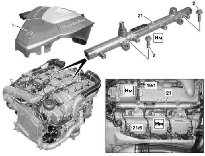
Fuel Distribution Line Installation Details (M628)
1 - Air purifier; 2 - Bolts; 19/1 - Pressure line/valve block/fuel line; 21 - Fuel line; 21/6 - Fuel lines of injectors
1. Remove the air cleaner (see Section Servicing air intake tract components).
2. Remove the injector fuel lines (21/6) and the pressure fuel line (19/1).
[Publication taken from an online resource: mercedesman.ru]
3. Unscrew the bolts (2) and remove the fuel line (21).
4. Installation is carried out in the reverse order - tighten the fastening bolts only after installing the pressure lines.
5. Finally, start the engine and check the fuel system components for signs of developing leaks, clear the memory of the on-board diagnostic module (see Chapter Engine electrical systems).
Nozzles
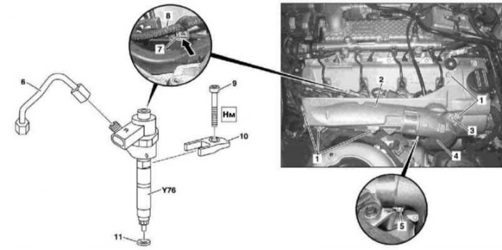
Injector installation details (M628)
1 - Screw; 2 - Lid; 3 - Screw; 4 - Boost tract air intake duct; 5 - Screw; 6 - Fuel line of the injector; 7 - Retainer; 8 - Oil drain line; 9 - Screw; 10 - Retainer; 11 - Sealing ring; Y76 - Injector
1. Remove the air cleaner (see Section Servicing air intake tract components).
2. Remove the air intake assembly with the MAF sensor (see Section Servicing air intake tract components).
3. Unbolt and move aside the left air intake duct (4) (see Section Servicing air intake tract components).
4. Remove the right and left injector covers (2).
5. Disconnect the electrical wiring and fuel lines from the injectors (6).
6. Release the clamps (7), then remove and move aside the oil drain lines (8).
Attention! The fasteners must be replaced!
7. Remove the clamps (10) and remove the injectors (Y76).
8. Installation is carried out in the reverse order - do not forget to replace the sealing elements.
9. Finally, start the engine and check the fuel system components for signs of developing leaks, clear the memory of the on-board diagnostic module (see Chapter Engine electrical systems).