
For models 463.333 (M628)
Attention! Self-locking fasteners must be replaced without fail!
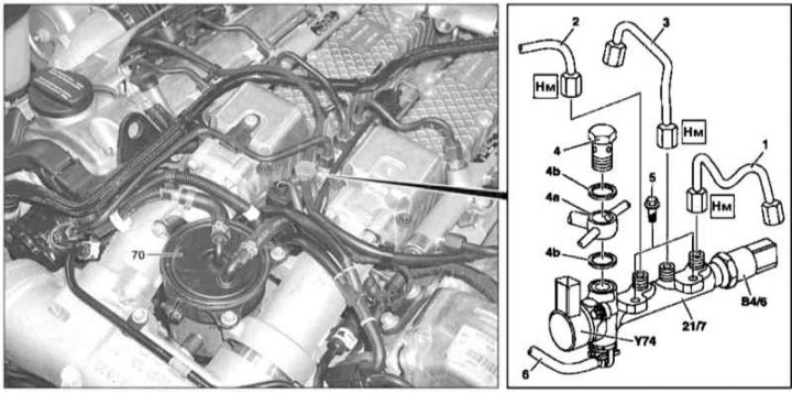
Valve installation details (M628)
1, 2, 3 - Pressure lines of the fuel path; 4 - Hollow bolt of the union connection; 4a - Union connector; 4b - O-rings; 5 - Screw; 6 - Fuel return line; 70 - Fuel filter; 21/7 - Valve assembly; B4 / 6 - Pressure sensor in the fuel line; Y74 - Pressure control valve
1. Turn off the ignition.
2. Open the hood and lock it in an upright position.
3. Remove the air cleaner (see Section Servicing Air Inlet Components).
4. Remove the oil filler trim panel.
5. Remove the fuel filter (70).
6. Disconnect the wiring from the pressure sensor in the fuel line (В4/6) and pressure control valve (Y74).
7. Disconnect pressure fuel lines (1, 2 and 3), - plug the open ends of the lines / fittings immediately, collect traces of spilled fuel, prepare replacement sealing elements.
8. Remove the hollow bolt (4) and remove the plug (5).
Attention! O-rings (4b) must be replaced without fail!
9. Turn out fixing bolts (5) and remove the valve assembly (21/7) complete with a return line connected to it (6).
10. Disconnect from valve assembly (21/7) return line (6), - prepare a replacement sealing ring.
11. Installation is carried out in the reverse order - do not forget to replace the sealing elements.
Note. Final tightening of union nuts of pressure fuel lines (1, 2 and 3) should only be done after tightening the bolts (5).
12. Start the engine and check the power system components for signs of leaks. In conclusion, clear the memory of the on-board self-diagnosis module (see chapter Engine Electrical Systems).