
Models 463.323 (M612)
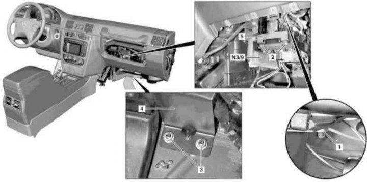
Installation details of the CDI control module on models 463.323 (M612) (1 of 2)
1, 3 - Nuts; 2 - Screw; 4 - Support bracket; 5 - Connector; N3/9 - CDI control module
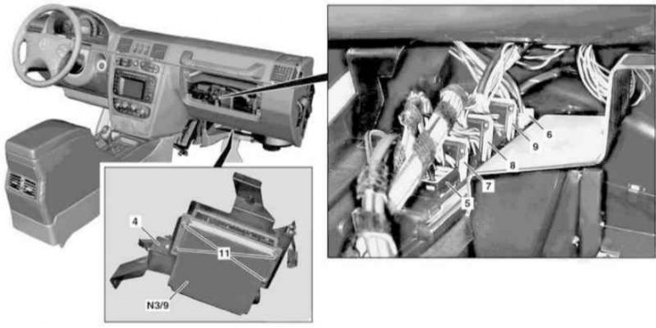
Installation details of the CDI control module on models 463.323 (M612) (2 of 2)
6, 7, 8, 9 - Connectors
11 - Screw
1. On models of the corresponding configuration (code ET2) activate the service mode of the TELE AID emergency call system (see Section Activation / deactivation of the service mode of the TELE AID emergency call system).
2. Turn on the auxiliary battery and connect it to the standard battery, then disconnect the negative wire from the latter and insulate the pole terminal. If the battery is removed from the vehicle, disconnect the positive cable from the battery as well.
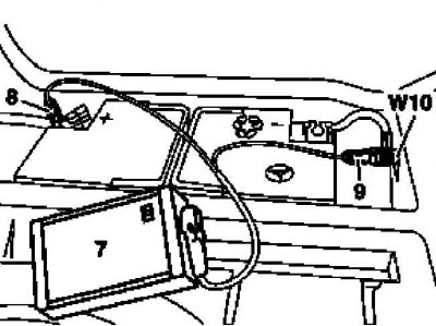
7 - Auxiliary battery
8 - Module positive wire terminal
9 - Terminal of the negative wire of the module
W10 - Battery Ground
3. Remove the carpet panel in the right front footwell.
4. Without disconnecting the electrical wiring, dismantle the front signal sensing and activation module (SAM) (see chapter Onboard electrical equipment).
5. Give the nut (1).
6. Having previously unscrewed the screws (2), remove the bracket (5).
7. Give nuts (3) and unplug the connectors (5, 6, 7, 8 and 9), - do not forget to release the latches where they are provided.
8. Moving down and back, remove the CDI control module from the instrument panel (N3/9).
9. Turn out bolts (11) and separate the module from the support bracket (4).
10. Installation is carried out in the reverse order, - with the appropriate configuration (code ET2) deactivate the service mode of the TELE AID system (see Section Activation / deactivation of the service mode of the TELE AID emergency call system).
11. Finally, read the DTCs and clear the OBD memory (see chapter Engine Electrical Systems).
Models 463.333 (M628)
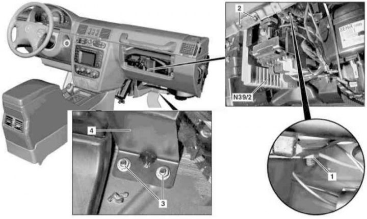
Installation details of the CDI control module on models 463.333 (M628) (1 of 2)
1, 3 - Nuts
2 - Screw
4 - support bracket
N3/9 - CDI control module
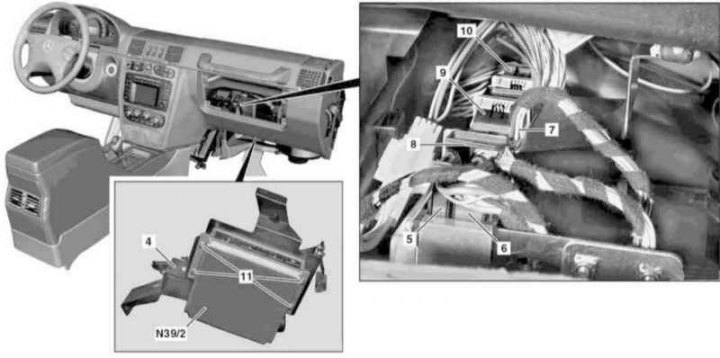
Installation details of the CDI control module on models 463.333 (M628) (2 of 2)
5, 6, 7, 8, 9,10 - Connectors
11 - Screw
1. On models of the corresponding configuration (code ET2) activate the service mode of the TELE AID emergency call system (see Section Activation / deactivation of the service mode of the TELE AID emergency call system).
2. Turn on the auxiliary battery and connect it to the standard battery, then disconnect the negative wire from the latter and insulate the pole terminal. If the battery is removed from the vehicle, disconnect the positive cable from the battery as well.

7 - Auxiliary battery
8 - Module positive wire terminal
9 - Terminal of the negative wire of the module
W10 - Battery Ground
3. Remove the carpet panel in the right front footwell.
4. Without disconnecting the electrical wiring, dismantle the front signal sensing and activation module (SAM) (see chapter Onboard electrical equipment).
Note. The SAM module is removed assembled with the fuse/relay mounting block.
5. Give the nut (1).
6. Remove the screws (2).
7. Give nuts (3).
8. Disconnect connectors (5, 6, 7, 8, 9 and 10), - do not forget to release the latches where they are provided.
9. Moving down and back, remove the CDI control module from the instrument panel (N39/2).
10. Turn out bolts (11) and separate the module from the support bracket (4).
11. Installation is carried out in the reverse order, - with the appropriate configuration (code ET2) deactivate the service mode of the TELE AID system (see Section Activation / deactivation of the service mode of the TELE AID emergency call system).
12. Finally, read the DTCs and clear the OBD memory (see chapter Engine Electrical Systems).