
Control device
The control device is located in the lower part of the body under the glove box.
Remove the right side of the body upholstery.
Pull out the spring clip (1) and remove the control unit from the holder (see fig. 151).
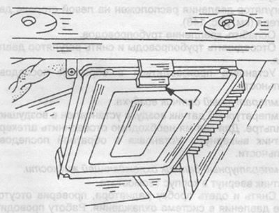
Pic. 151. Removing the control device.
Open the wire clamp in the car body.
Remove plastic cover.
Carefully disconnect the multi-position plug from the control unit.
Installation is carried out in reverse order.
Pressure meter
The pressure sensor is located on the mudguard of the wheel.
Disconnect the multi-position plug.
Loosen the fastener and remove the hose.
Loosen the mounting screws and remove the sensor.
Installation is carried out in the reverse order.
Throttle switch
Throttle switch mounted on the side of the throttle body (see fig. 152).
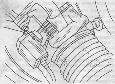
Pic. 152. Throttle switch mount.
Loosen the two fixing screws.
Remove switch.
When installing the switch, the plug must point forward. Fix the switch with screws without much effort. Check the position of the plug in relation to the socket. Carry out the necessary adjustments and connections to the switch at a service station.
Pressure regulator
The pressure regulator is located on the left side of the engine (see fig. 148).
Loosen piping.
Disconnect the pipes and remove the pressure regulator.
Installation is carried out in the reverse order.
Air temperature sensor
The air temperature sensor is installed in the air filter. To remove, disconnect the plug and unscrew the sensor. Installation in reverse order.
Coolant temperature sensor. The sensor is screwed into the thermostat housing.
Remove and put on the radiator cap, checking the absence of pressure in the cooling system. Work on a cold engine.
Disconnect plug from sensor.
Unscrew the temperature sensor, install a new O-ring when installing.
Installation in reverse order. Ignition distributor - impulse switch.
The impulse switch is located at the bottom of the ignition distributor (see fig. 137).
Disconnect the multi-position plug.
Loosen the two fixing screws and remove the switch.
Lubricate moving parts with Bosch Ft 1 v 4 grease before installation. Contact adjustment is not required. Pay attention to the position of the plug before installation.
Cold start nozzle
The injector is located on the intake manifold.
Disconnect plug.
Place a clamp on the fuel hose.
Loosen the clamp and disconnect the hose.
Loosen the mounting bolts and remove the injector.
Installation in reverse order. When assembling, install a new gasket.
Auxiliary air valve
Auxiliary air valve mounted on the cylinder head (see fig. 153). Air is supplied to the valve from the air filter through a plastic hose.
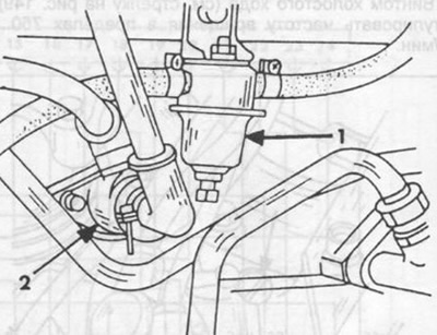
Pic. 153. The valve for supplying additional air.
1 - diaphragm damper,
2 - additional air valve.
Disconnect hose.
Loosen the mounting bolts and remove the valve.
Installation in reverse order.
Nozzles
The injectors are installed in the inlet channels of each cylinder directly in front of the inlet valve and fixed in pairs in the holder (see fig. 154). Removing the injectors in pairs.
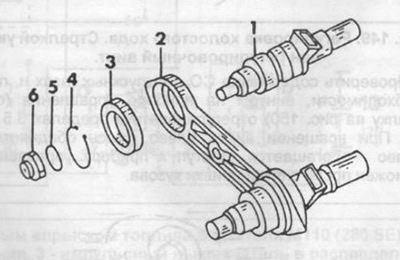
Pic. 154. Nozzle and holder.
1 - nozzle,
2 - holder,
3 - rubber ring,
4 - adjusting ring,
5 - sealing ring,
6 - insulating cap.
Disconnect the plug.
Disconnect fuel lines from injectors.
Loosen the holder fixing nut.
Remove the two nozzles together with the holder.
When installing, insert the nozzle into the nozzle holder and put on the rubber ring on the nozzle body from the atomizer side. Check the position of the ring and install the adjusting ring.
Install the sealing rubber ring on the housing. When overhauling, always replace the ring.
Install the holder with two nozzles and tighten the fastening nut to a torque of 10 Nm. Do not damage the atomizer during installation.
Connect fuel lines.
Install the plug and put on the rubber protective cap.
Thermo-time switch
The thermo-time switch is located on the right side of the cylinder head (see fig. 155).
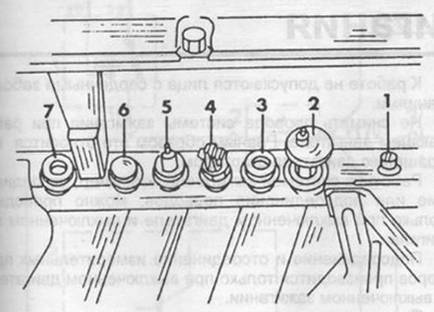
Pic. 155. Thermo-time switch on the M110 engine.
1 - coolant temperature sensor,
2 - temperature switch 100°С,
3 - plug,
4 - thermo-time switch,
5 - thermometer sensor,
6 - reserve,
7 - plug.
Carry out work on a cold engine and in the absence of excess pressure in the cooling system.
Disconnect wires.
Unscrew the switch.
Installation in reverse order.
Fuel pump and filter
The fuel pump and filter are mounted on the body floor panel between the fuel tank and final drive.
Remove protective mudguard.
Clamp fuel hoses to prevent fuel leakage.
Loosen the clamps and remove the hoses.
Disconnect wires.
Remove fuel pump or filter.
Installation in reverse order.