
Fuel pump
The fuel pump delivers fuel from the fuel tank to the injectors and to the starting injector and at the same time maintains pressure in the fuel system. Rotary type pump driven by an electric motor. An eccentrically located rotor rotates in a cylindrical body. Along the circumference of the rotor there are semicircular grooves in which metal rollers are installed. When the rotor rotates, the rollers are pressed against the cylindrical surface of the housing and act as a seal. The principle of operation of the pump is that when the rotor rotates, the rollers form a larger volume in the intake valve area, and a smaller volume in the exhaust valve area. A pressure limiting and fuel drain valve is installed on the pump outlet pipe, which prevents pressure drop in the system when the engine is turned off. On the other hand, the valve limits the pressure within 3...4 atm. The ventilation system in the valve prevents air from entering the power system. The fuel pump is located next to the fuel tank (see fig. 133). Pump performance at 12 V and 2500 rpm. and a pressure of 2 atm. is 120 l/h.
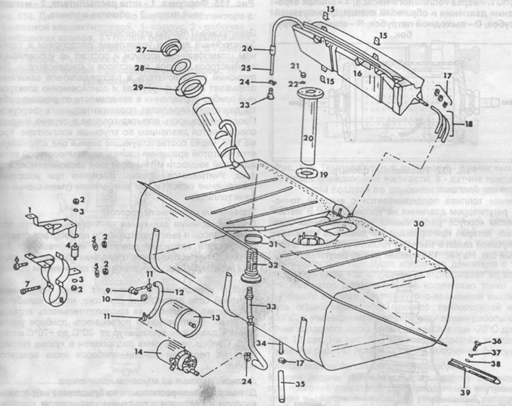
Pic. 133. Details of the fuel tank.
1 - bracket,
2 - nut,
3 - spring washer,
4 - buffer,
5 - washer,
6 - screw with a cylindrical head,
7 - screw with a cylindrical head,
8 - clamp,
9 - angle fitting,
10 - sealing ring,
11 - collar,
12 - fuel hose,
13 - fuel filter,
14 - fuel pump,
15 - clamp nut,
16 - distribution tank,
17 - collar,
18 - fuel hose,
19 - gasket,
20 - pipe,
21 - nut,
22 - puck,
23 - rubber cuff,
24 - collar,
25 - ventilation tube,
26 - rubber tube,
27 - fuel tank cap,
28 - gasket,
29 - rubber nozzle,
30 - fuel tank,
31 - sealing ring,
32 - hollow bolt with filter,
33 - suction hose,
34 - fuel outlet,
35 - fuel hose,
36 - bolt,
37 - spring washer,
38 - washer,
39 - reinforcing bar.
Fuel filter
The fuel filter is located in a metal housing. On two sides of the body there are connecting pipes. The filter element is replaced after 40,000 km. When installing, observe the direction of fuel flow (arrows in fig. 132).
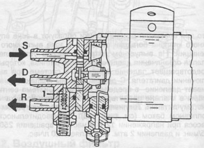
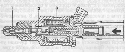
Pic. 131. Section of the fuel pump.
1 - pressure limiting valve and check valve,
S - outlet pipe,
D - outlet pipe,
R - drain pipe.
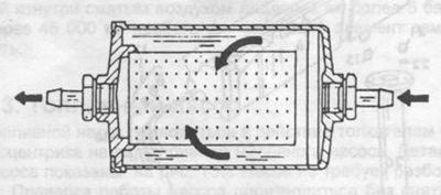
Pic. 132. Fuel filter.
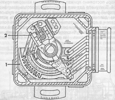
Pressure regulator
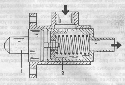
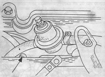
The fuel pressure is maintained with high accuracy by a pressure regulator at the level of 2 atm. A spring-loaded diaphragm is located in the metal case. which, when the pressure is exceeded, opens the bypass channel and excess fuel is drained into the fuel tank. On fig. 134 shows a section of the regulator.
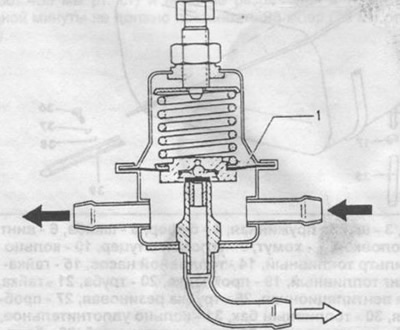
Pic. 134. Pressure regulator.
1 - aperture.
Nozzles
Electromagnetic nozzles are used for dosing and spraying fuel. The nozzle consists of a nozzle body and a spring-loaded dosing needle with a magnetic anchor. When the electromagnet is turned on, the needle moves away from the seat by 0.1... 6 mm, and fuel enters through a calibrated annular target. When the winding is de-energized, the needle is lowered onto the saddle under the action of the spring. At the front end of the needle, a bevel is made to spray fuel. On fig. 135 shows a section of the nozzle with the details described.
Pic. 135. Nozzle.
1 - spray needle,
2 - magnetic anchor,
3 - magnet winding.
Electronic control device
The electronic control device is located in a steel stamped case and consists of controlled transistors, diodes, resistors and capacitors. The pulse switch in the ignition distributor opens the needles in the injectors and at the same time the electronic control device, depending on the engine operating mode, determines the duration of the injectors. The duration of fuel injection is primarily determined by the pressure in the intake manifold. In addition, through the appropriate links, it is corrected by the engine speed, coolant temperature and intake air temperature. The mode of movement during acceleration is taken into account (mixture enrichment) and when slowing down (fuel reduction).
Fuel pump control
After the ignition is turned on, the fuel pump turns on for 1 second and turns off if the starter does not work or the engine speed does not exceed 100 rpm. This prevents fuel from entering the cylinders of an idle engine when the ignition is on.
The control device also corrects the voltage of the vehicle's on-board network so that voltage fluctuations do not affect the duration of fuel injection. The temperature error of the control device in the temperature range from -30°С to +70°С is less than±2%. The control device is located in the car body on the front instrument panel below the glove box.
Intake manifold pressure sensor
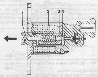
The pressure sensor is located on the mudguard above the right wheel and is connected to the intake manifold with a short hose. In the sensor housing there are two membrane chambers connected to each other, one chamber is working, the other communicates with the atmosphere through a hollow bolt. When the cameras move, the armature moves relative to the winding, changing its inductance. The change in inductance as a function of the pressure in the inlet pipe is transmitted to the control unit.
The armature is constantly pressed against the membrane chambers by a spring. A throttle-damper is located in the sensor fitting, which reduces fluctuations in the system due to pressure pulsation in the intake manifold. The throttle is installed in a safety valve with a large cross section. With a sharp opening of the throttles, the valve provides a quick response of the sensor to a change in pressure. On fig. 136 shows a section of the sensor.
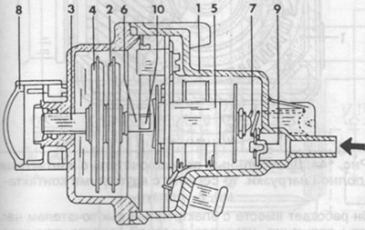
Pic. 136. Pressure sensor in the intake manifold with height adjustment.
1 - body,
2 - working membrane chamber,
3 - hollow bolt,
4 - membrane chamber for adjusting the height of the terrain,
5 - winding,
6 - anchor,
7 - spring,
8 - plug,
9 - safety valve with throttle-damper,
10 - anchor damper.
Impulse switch
On fig. 137 shows an impulse switch that controls the opening of the injectors and the start of injection.
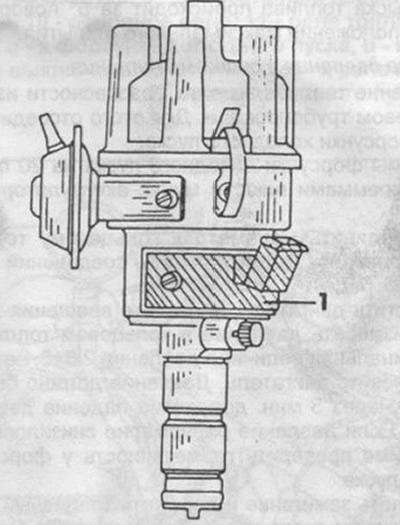
Pic. 137. Ignition distributor with remote impulse switch (1).
An external pulse switch is located in the lower part of the ignition distributor housing. Two contact switches located at an angle of 180°are driven from an eccentric on the ignition distributor shaft. Each switch controls the operation of a group of nozzles. On fig. 138 shows a section (view from above) ignition distributor with built-in impulse switch.
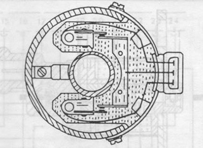
Pic. 138. Movable contact switches.
Temperature sensor
The temperature sensor works as a resistance, the value of which changes depending on the temperature, and is located in a protective case with good thermal conductivity. The housing is made in the form of a bolt with a hexagonal head. Sensors measure the temperature of the coolant and air in the intake manifold, and through the control device regulate the fuel supply depending on these parameters. On fig. 139 shows temperature sensors.
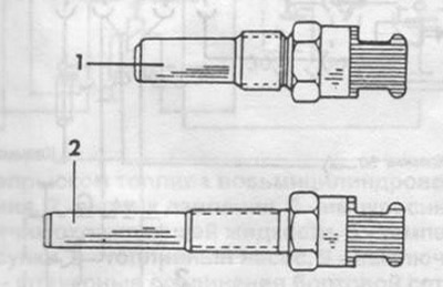
Pic. 139. Temperature sensors.
1 - coolant temperature sensor,
2 - air temperature sensor in the intake manifold.
Cold start nozzle
The cold start injector is located on the intake manifold and is connected to the fuel line. The nozzle is controlled by an ignition switch and a temperature-time switch, which is washed by the coolant. When starting a cold engine with a temperature below +35°C, the injector injects an additional amount of finely atomized fuel into the intake manifold. The temperature-time switch limits this process with a temperature below +35°C, with a decrease in temperature, the operation time of the cold start injector increases and at -20°C it reaches 12 seconds. On fig. 140 shows a cold start injector. On fig. 141 shows the nozzle switching circuit.
Pic. 140. Cold start nozzle.
1 - threaded jet,
2 - magnet winding,
3 - anchor,
4 - gasket.
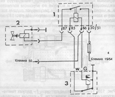
Pic. 141. Scheme of switching on the cold start injector.
1 - relay,
2 - cold start nozzle,
3 - temperature-time switch.
Auxiliary air valve
The auxiliary air valve turns on when the engine warms up. To overcome internal friction in the engine, increased fuel consumption is required. The necessary additional air passes through the filter in the engine compartment, through the control valve, bypassing the throttle. The thermoelement washed by the coolant, depending on the temperature, changes the valve flow area and, accordingly, the amount of air. The valve is fully open below -20°C and fully closed at +65°C. On fig. 143 shows a cross-section of the auxiliary air supply valve.
Pic. 143. Valve for supplying additional air.
1 - thermoelement,
2 - valve.
Pic. 144. Throttle switch with full load contacts.
1 - segment with circular contacts,
2 - slider.
It works in conjunction with an electronic speed switch to control fuel delivery during variable driving. The switch lengthens the duration of the pulse and increases the duration of the injection in order to compensate for the inertia of the pressure sensor. Ground contacts slide over a segment with several circular contacts that change the injection pulse as needed. The ground contacts are connected to a slider, with the help of which the mixture is enriched only during acceleration. The slider through the double ground contacts at full throttle provides the composition of the mixture for full load. With this control method, a sharp increase in fuel injection occurs after 5°of throttle rotation to the maximum opening position.
Checking the pressure in the power system
The fuel pressure is measured in the ring pipeline for safety reasons. To do this, disconnect the plug from the cold start injector.
The cold start injector terminals are connected to the plus and minus terminals of the battery for 20 seconds.
Connect a pressure gauge to the ring fuel line. Check fuel line connections for leaks.
Start the engine at idling speed and measure the pressure in the fuel ring. Nominal pressure value 2.0+0.1 atm.
Stop engine. The pressure should be about 1.7 atm. After 5 min. a pressure drop of up to 1.5 atm is permissible. If the pressure evenly decreased to 0, then it is necessary to check the tightness of the cold start injector
Turn on the ignition and pinch the fuel hose at the cold start injector (see fig. 146). If fuel pressure persists, the injector is leaking and should be replaced.
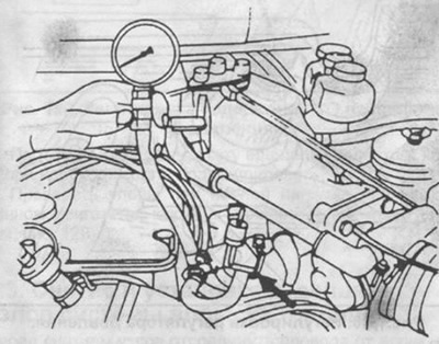
Pic. 146. Checking the cold start injector.
Checking the pressure regulator
Switch on the ignition and, after turning off the fuel pump, pinch the fuel drain hose from the regulator. A persistent fuel pressure is a sign of a leaky pressure regulator and should be replaced.
Check ball valve at fuel pump outlet.
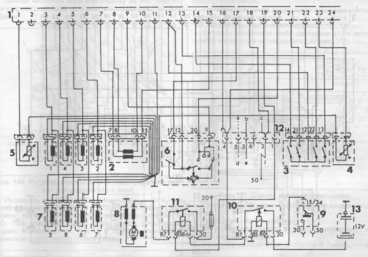
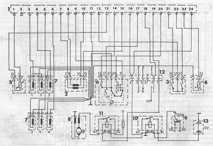
Pic. 142. Scheme of switching on the control device for electronic fuel injection of an eight-cylinder engine (350 SE/450 SE).
1 - contact strip of the control device,
2 - pressure sensor,
3 - pulse switch in the ignition distributor,
4 - coolant temperature sensor,
5 - air temperature sensor,
6 - throttle switch,
7 - nozzles,
8 - fuel pump,
9 - ignition switch,
10 - main relay,
11 - fuel pump relay,
12 - plug connections of the vehicle's on-board network,
a - to the cold start nozzle,
b - to the thermo-time switch terminal W,
c - to the thermo-time switch terminal G,
d - to cold start relay terminal 87,
e - to the cold start relay terminal 85,
f - to cold start relay terminal 86,
13 - battery.
Switch on the ignition and, after turning off the fuel pump, pinch the fuel hose supplying fuel to the damper. Maintaining pressure is a sign that the fuel pump needs to be replaced.
Checking the injectors
Remove injectors with ring fuel line. Unfasten and remove the control unit under the glove box. Remove the fuel pump relay (arrow in fig. 147) and bridge tips 1 and 3. The fuel pump is connected to tip 1. Turn on the ignition and the fuel pump will work with the engine off.
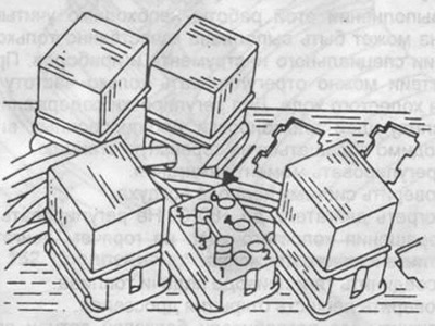
Pic. 147. Checking the nozzles.
Pic. 145. Scheme of switching on the electronic fuel injection control device of the M110 engine (280 SE).
1 - contact strip of the control device,
2 - pressure sensor,
3 - pulse switch in the ignition distributor,
4 - coolant temperature sensor,
5 - air temperature sensor,
6 - throttle switch,
7 - nozzle,
8 - fuel pump,
9 - ignition switch,
10 - main relay,
11 - fuel pump relay,
12 - plug connection of the vehicle's on-board network,
a - to the cold start nozzle,
b - to the thermo-time switch terminal W,
c - to the thermo-time switch terminal G,
d - to cold start relay terminal 87,
e - to the cold start relay terminal 85,
f - to cold start relay terminal 86,
13 - battery.
Start the engine at idle speed and adjust the fuel pressure with a screw on the pressure regulator to 2.0 + 0.1 atm. (pic. 148). If no change in pressure is noted after turning the adjusting screw, the pressure regulator must be replaced. Before removing the pressure gauge, it is necessary, as already indicated, to relieve the fuel pressure.
Pic. 148. Adjustment of the pressure regulator.