
Warning: Before working on any part of the power system, read the precautions in paragraph 1.
Note: After replacing or installing parts of the power system, it is recommended to carry out diagnostics at a service station. Such a check will destroy the erroneous codes that may be contained in the memory of the electronic control unit of the power system.
Fuel distributor
Removing
1. Depressurize the power system as described in paragraph 2. Disconnect the negative battery terminal.
2. Remove the air cleaner as described in paragraph 3.
3. Turn away the union of the bringing line of atomizers on the distributor and atomizers. When loosening the nuts, hold the nozzle with a wrench.
4. On the fuel distributor, unscrew the line fitting from the cold start valve, pressure regulator and fuel supply pipe.
5. Disconnect the harness connector from the hydraulic pressure regulator at the multi-pin connector on the side of the distributor.
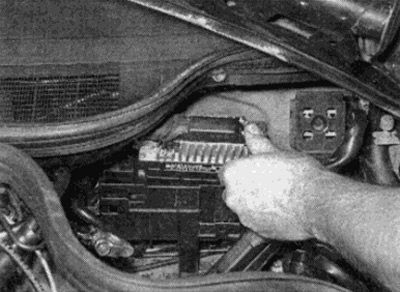
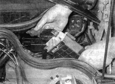
6. Remove the three screws securing the top of the fuel distributor, then lift the assembly up by turning it from side to side to separate it from the airflow sensor (see fig. 10.6, a, b). Remove the sealing ring.
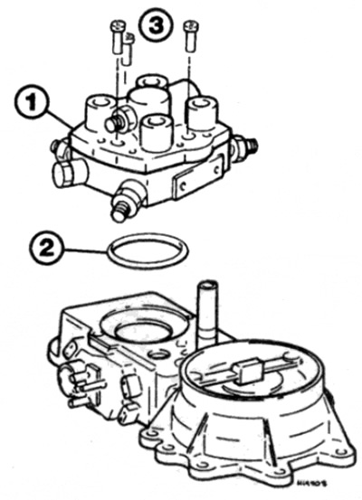
Pic. 10.6, a. Details of fastening of the fuel distributor assembly to the air flow sensor (4 cylinder engine)
1 fuel distributor
2 O-ring
3 Mounting screws
Pic. 10.6b. Screws for fastening the fuel distributor assembly to the air flow sensor (6 cylinder engine)
Installation
7. Installation is carried out in the reverse order. Install a new O-ring between the distributor and the air flow sensor. Where provided, tighten all connections to the required torque.
8. When finished, start the engine and check for leaks around the removed parts. Then check and adjust the idle speed. and CO content in exhaust gases (see chapter 1A).
Air flow sensor
Removing
9. Refer to the relevant paragraphs of this paragraph and remove the distributor and fuel pressure regulator.
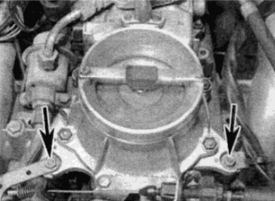
10. Remove the bolts and move the linkage bracket to the side (see fig. 10.10).
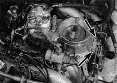
Pic. 10.10. Throttle linkage bracket bolts (shown by arrows)
11. Disconnect the airflow sensor harness connector from the multi-pin connector (see fig. 10.11).
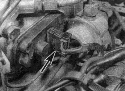
Pic. 10.11. Air flow sensor connector (shown by arrow)
12. As described in paragraph 9, separate the throttle body from the base of the airflow sensor assembly (see fig. 10.12)
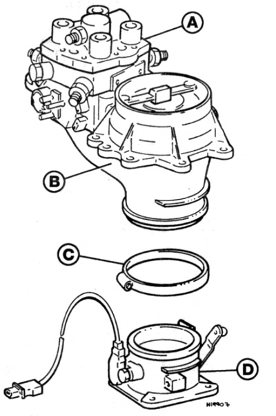
Pic. 10.12. Details of fastening the air flow sensor to the throttle body (4 cylinder engine)
A Fuel distributor
The air flow sensor
C Clamp
D Throttle body
13. Turn away nuts of fastening of the gauge of an air stream to rubber support and an arm (see fig. 10.13).
Pic. 10.13. Nuts for attaching the air flow sensor to the rubber mounts (shown by arrows)
14. Remove the assembly from the housing, disconnect the idle air hose and remove the air flow sensor assembly from the engine compartment.
15. After unscrewing the screws, the rubber guide molding can be separated from the sensor housing. Please note, however, that the screws vary in length and must be installed exactly in place during assembly.
Installation
16. Installation is carried out in the reverse order. Where required, tighten all fasteners to the correct torque.
17. When finished, start the engine and check for leaks around the removed parts. Then check and adjust the speed xx. and CO content in exhaust gases (see chapter 1A).
Air intake pump (only on 6-cylinder engines)
Removing
18. Disconnect the negative battery terminal.
19. Loosen the accessory drive belt as described in Chapter 1 and remove the belt from the air intake pump pulley.
20. Disconnect the plug of the electromagnetic clutch from the block.
21. Loosen the clamp and remove the air hose from the fitting on the back of the pump.
22. Turn away the top and bottom bolts of fastening. Then remove the pump from the engine.
Installation
23. Installation is carried out in the reverse order. When finished, contact Chapter 1 and tighten the belt.
Cold start valve
Removing
24. Depressurize the power system as described in paragraph 2. Disconnect the negative battery terminal.
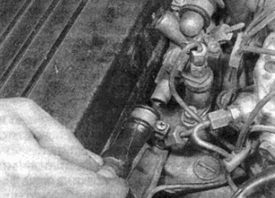
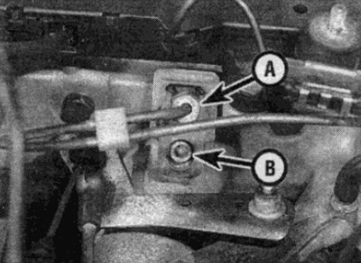
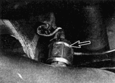
25. Disconnect the cold start valve plug from the block, which is located on the intake manifold close to the mating surface with the cylinder head (see fig. 10.25).
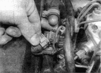
Pic. 10.25. Disconnecting the Cold Start Riveter Connector
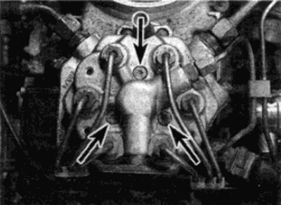
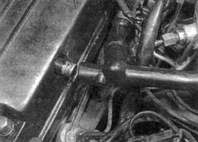
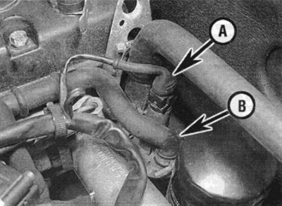
26. Loosen and unscrew the fuel line fitting nut, then disconnect the fuel line from the valve and fuel distributor (see fig. 10.26). Get ready for some of the gasoline to leak out - substitute a container.
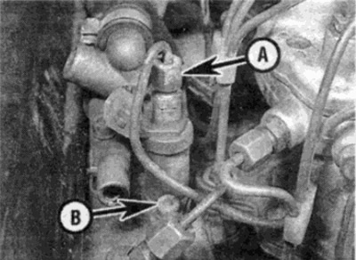
Pic. 10.26. Nut of the union of a fuel line on the valve of start-up of the cold engine (A) and front valve screw (IN)
27. Remove the two Allen screws and lift the valve. Remove the pad.
Installation
28. Installation is carried out in the reverse order.
Coolant temperature sensor
Removing
29. Refer to Chapter 3 and partially drain the cooling system. Make sure the ignition is off.
30. The fluid temperature sensor is screwed into the top surface of the cylinder head on the left side of the engine. Do not confuse it with the temperature gauge sensor.
31. Disconnect the connector from the sensor.
32. Turn out the gauge from the case and remove a sealing ring.
Installation
33. Installation is carried out in the reverse order. When finished, add coolant.
Throttle switch
Removing
34. The switch can be disconnected after removing the throttle body - refer to paragraph 9. Recall that when replacing the switch is selected to the throttle body. This work is best left to a Mercedes-Benz dealer or a Bosch fuel injection specialist.
Electronic control unit OBU
Removing
Caution: Electronic control unit (ECU) contains parts that are sensitive to the level of static electricity generated by humans during normal operation. With the harness connector disconnected, loose contacts are free to conduct static electricity to these parts, rendering them inoperable or even damaging them. Damage may not be noticeable and not immediately manifest. Costly repairs can be avoided by following these basic rules:
- A) Hold the ECU only by the body: do not touch the contacts of the unit with your fingers or tools.
- b) When working on the ECU, ground yourself from time to time by touching metal objects such as unpainted water pipes. This will allow the static electricity to drain from your body.
- V) Do not leave the ECU disconnected longer than necessary for operation.
35. The ECU is located in a compartment behind the partition of the engine compartment next to the battery.
36. Disconnect the negative battery terminal. On some models, the battery must be removed to provide sufficient space (see chapter 5A).
37. To disconnect the multi-pin connector, first compress the spring plates on the cable lug of the junction block, lift the block from the cable side, then separate the boss at the opposite end of the block.
38. Press the latch, then unscrew the screws (where provided) and remove the computer from the supports (see fig. 10.38, a, b). Please note that on some models with ABS, the ABS electronic control box must first be removed - refer to Chapter 9.
Pic. 10.38 a. Press the retainer off the camshaft cover...
Pic. 10.38, b - then pull out the computer and disconnect the connector plug
Installation
39. Installation is carried out in the reverse order.
Fuel injectors
Removing
40. Depressurize the power system as described in paragraph 2. Disconnect the negative battery terminal.
41. Remove the air cleaner cover as described in paragraph 3 and, where required for improved access, disconnect the hoses from the camshaft cover and auxiliary air assembly (see fig. 10.41, a, b).
Pic. 10.41 a. Disconnect the hoses from the camshaft cover...
Pic. 10.41, b - and additional air unit - 4-cylinder engine
42. Loosen the fuel line union nuts on each injector and the corresponding fitting on the fuel distributor. When loosening the nuts, hold the nozzles with a wrench. Move fuel lines out of work area.
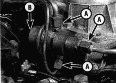
43. On 4-cylinder engines, loosen the center nut and remove the connecting link between each pair of injectors. On 6-cylinder engines, loosen and remove the screw, then remove the injector clamp (see fig. 10.43, a, b).
Pic. 10.43. A. Injector assembly - 6-cylinder engine
A Fuel line union nut
C Clamp fixing screw
Pic. 10.43. b. Injector assembly - 4-cylinder engine
A Fuel line union nut
Injector link nut
44. Remove the nozzles by removing the seals.
Installation
45. Installation is carried out in the reverse order. Use new injector gaskets. Tighten the fastening screws securely.
Fuel pressure control
Removing
46. Depressurize the power system as described in paragraph 2. Disconnect the negative battery terminal.
47. Remove the air cleaner as described in paragraph 3.
48. Pinch the flexible fuel hoses that go to the pressure regulator. Do not use a vise as they may damage the hoses from the inside.
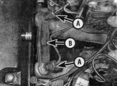
49. Unscrew the fittings of the fuel lines and separate the fuel pipes from the sockets on the pressure regulator (see fig. 10.49). Be prepared that some of the gasoline may spill. Where provided, disconnect the vacuum hose from the back of the regulator.
Pic. 10.49. Fuel pressure regulator connections
A Fuel line fittings
V Vacuum hose
50. Loosen and remove the clamp bolt, then remove the pressure regulator from the airflow sensor housing.
Installation
51. Installation of the pressure regulator is carried out in the reverse order.
Auxiliary Air Assembly / Idle Actuator
6-cylinder engines
52. Disconnect the negative battery terminal.
53. The actuator is located on top of the intake manifold in front of the fuel distributor.
54. Disconnect the plug from the block on the mechanism.
55. Remove the air hoses from the actuator fittings, marking them for ease of installation.
56. Remove the bolts and remove the mechanism from its supports (see fig. 10.56).
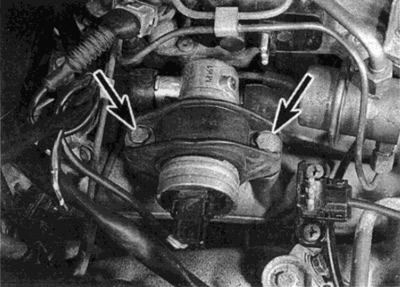
Pic. 10. 56. Idle actuator mounting bolts - 6-cylinder engine
57. Installation is carried out in the reverse order. Make sure that the hoses are connected correctly, as they were before removal.
4-cylinder engines
58. Disconnect the negative battery terminal.
59. The auxiliary air unit is located at the rear of the intake manifold near the bulkhead of the engine compartment.
60. Disconnect the wire from the node block (see fig. 10.60).
Pic. 10. 60. Auxiliary air valve plug (A) and air hose (IN) – 4-cylinder engine
61. Loosen the hose clamp and remove the air hose from the fitting on top of the auxiliary air valve.
62. Turn away bolts and remove the valve from support.
63. Installation is carried out in the reverse order.
Lambda probe
Removing
64. Lambda probe (oxygen sensor) located in the ledge of the exhaust pipe - access to it opens from the bottom of the car.
65. Raise the front of the car with a jack and place it on stands (see "Lifting the vehicle and placing it on stands". You can place the car over a viewing hole or on a flyover.
66. Make sure the ignition is off and wait until the exhaust system is completely cool before starting work.
67. Operating from the bottom of the car, disconnect the wires of the Lambda probe from the block on the bottom tray. The connection is made in the form of a bayonet - to disconnect it, it is necessary to turn it a quarter of a turn counterclockwise.
Note: On later models, the connector is located inside the vehicle under the floor mat on the driver's side. Disconnect the connector and pull the wire through the baffle in the bottom tray.
68. Unfasten the metal shield, then use a wrench to unscrew the probe from the downpipe (see fig. 10.68).
Pic. 10.68. Unzip the metal case (shown by arrow) from lambda probe
Note: Since there is a dangling wire on the probe after disconnection and you do not have a wrench of the appropriate size, a split head will be required to remove the probe. Be careful not to damage the wire or tip of the removed probe.
Installation
69. Apply an anti-tack compound to the probe threads.
70. Install the probe into the body, tighten it to the required torque. Repair harness connection.