
Removing
1. Working in the engine compartment, disconnect the throttle cable from the guide arm by removing the square mounting block. Release the cable by passing it through the slot in the guide arm bracket (see fig. 7.1, a, b).
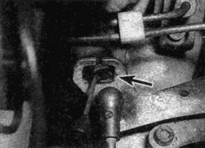
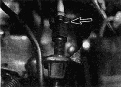
Pic. 7.1, a. Remove the square block (shown by arrow)
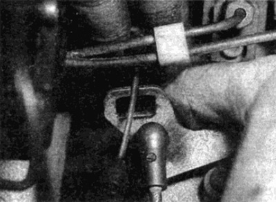
Pic. 7.1b....and release the cable by passing it through the groove in the guide arm bracket
2. Release the outer shell from the mounting bracket by depressing the tabs on the plastic retainer and remove it (see fig. 7.2).
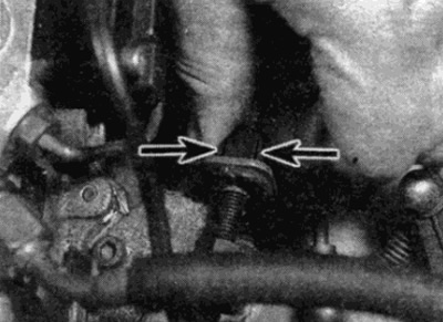
Pic. 7.2. To release the cable sheath, squeeze the tabs (shown by arrows) on a plastic holder
3. Working in the driver's footwell, disengage the return spring, then, where provided, remove the circlip and disconnect the cable from the top of the pedal arm (see fig. 7.3).
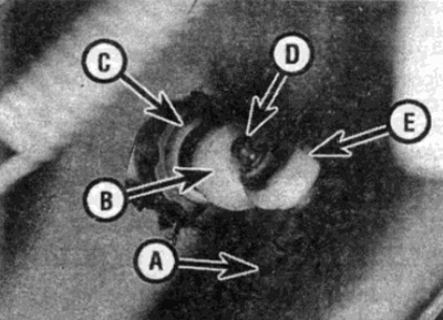
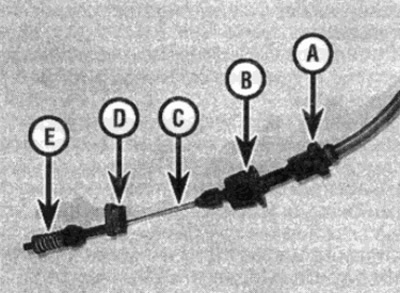
Pic. 7.3. Throttle cable and drop device
A Upper part of the throttle pedal
B Idle speed limiter adjusting nut
With sealing sleeve
D Lug for return spring
E Throttle pedal end
4. Gently push the cable sheath through the engine bulkhead bushing.
Note: Do not remove the grommet from the inner baffle.
5. From the side of the outer baffle, remove the rubber grommet, then pull the cable into the engine compartment through the grommet on the inner baffle.
Installation
6. Install cable in reverse order. Before connecting the cable to the throttle linkage, adjust the linkage and cable as described below (see fig. 7.6).
Pic. 7.6. Throttle Cable Assembly Parts - Throttle Link Side
Adjustment
Note: On vehicles equipped with a slip prevention system (ASR), precise adjustment of the linkage is a very difficult task. It is recommended that the adjustment be carried out by a Bosch fuel injection specialist or a Mercedes-Benz dealer.
7. Check that the throttle cable and linkage operate smoothly without binding or sticking. Check that the cable has no kinks throughout and. if necessary, lubricate the linkage.
8. At the throttle body, disconnect the throttle cable from the guide arm by removing the square mounting block. Pass the cable through the slot on the side of the guide arm.
9. Remove the connecting arm pins from the spherical seat on the guide arm. (The connecting lever is a flat adjustment lever that connects the guide lever to the throttle lever).
10. Move the guide lever until the roller rests against the idle speed limiter (see fig. 7.10). With the linkage in this position. loosen the pinch screw and adjust the length of the connecting arm, if necessary, ensuring that the guide arm fits stress-free onto the spherical seat.
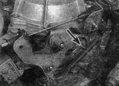
Pic. 7.10. Move the guide lever until the roller hits the idle speed limiter. (shown by arrow)
11. Connect the accelerator cable to the guide arm. On automatic transmission models, disconnect the pressure control cable from the control arm.
Models with Adjustable Full Throttle Stop Behind the Throttle Pedal
12. The rod at the inner end of the throttle cable must rest against the spring without play. Additionally, the guide lever must operate the idle microswitch against the tab. To achieve this, if necessary, turn the adjusting nut on the mounting bracket (see fig. 7.12. a-c).
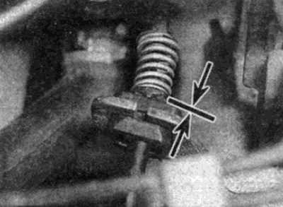
Pic. 7.12, a. The end of the throttle cable must rest against the spring without play
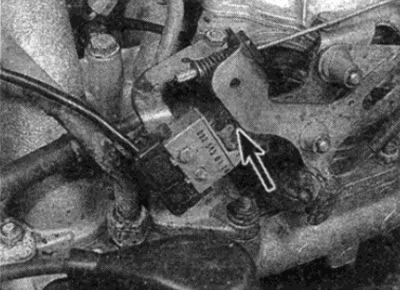
Pic. 7.12b. The guide lever must actuate the idle microswitch by resting on the tab (marked with an arrow)
Pic. 7.12, c. Throttle stop adjusting nut (shown by arrow) on support bracket
13. Loosen the limiter for the full opening of the damper in the niche under the driver's feet by turning the limiter finger to the left and pulling it out slightly.
14. Slowly depress the pedal until the throttle is fully open so that the throttle lever rests against the full throttle stop on the throttle body. Then release the pedal.
15. Lock the stopper by turning your finger to the left. Be careful not to push in or completely pull out your finger.
16. Repeat the checks described in paragraphs. 7-15, inclusive, and. adjust if necessary.
17. On vehicles with automatic transmission, install the pressure control cable and adjust its action as described in Chapter 7B.
Models without an adjustable stop behind the pedal
18. Have an assistant depress the accelerator pedal fully on vehicles with a manual transmission, or far enough to reach (but don't use) downshift switch on vehicles with automatic transmission.
19. The lever should touch the full throttle stop on the throttle body. If necessary, turn the adjusting nut on the bracket (see fig. 7.12. V).
20. Release the accelerator pedal again, allowing the linkage roller to rest against the idle speed limiter on the guide arm.
21. In this position, the rod at the end of the accelerator cable should rest against the spring without play. Additionally, the guide lever must operate the idle microswitch against the tab (see fig. 7.12, a and b). To achieve this, if necessary, turn the adjusting nut on the cable on the side of the accelerator pedal - the adjusting nut can be tightened from the niche under the feet on the driver's side (see fig. 7.3).
22. On vehicles with automatic transmission, install the pressure control cable and adjust its operation (see Chapter 7B).