
Cars BMW Cars Volkswagen Cars Chevrolet Cars Land Rover Cars Lada Cars Honda Cars Peugeot
English Русский
Български
Беларускі
Український
Српски
Hrvatski
Română
Polski
Slovenský
Magyar
Bookmark News and articles Sitemap Feedback Site search
MercedesMan.ru


A-Class C-Class E-Class G-Class M-Class S-Class Others
190 (W201) (1982-1993) W202 (1993-2000) W203 (2000-2007)
  • Main
  • C-Class
  • W201 (1982-1993)
  • Power unit
  • Injection system (gasoline)
  • Fuel pump(s) — removal and installation

Fuel pump(s) — removal and installation (Mercedes-Benz C-Class W201)

0
Contents: Removal ↡ Installation ↡

Removal


Warning: Before working on any part of the power supply system, read the safety precautions in paragraph 1.


1. The fuel pump is located underneath the floor hatch at the rear of the vehicle next to the fuel filter.

2. Contact paragraph 2 and depressurize the power supply system.

3. Disconnect the negative battery terminal.

4. With the vehicle on a level surface, apply the parking brake and place chocks under the front wheels. Jack up the rear of the vehicle and place it on supports (see Fig. "Lifting the car and placing it on supports").

5. Loosen the screws or unfasten the fasteners and remove the shield from the fuel pump, filter and battery (see Fig. 4.5, a-c).
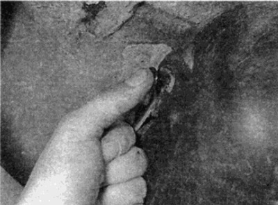
Fig. 4.5, a. Unfasten the fasteners...
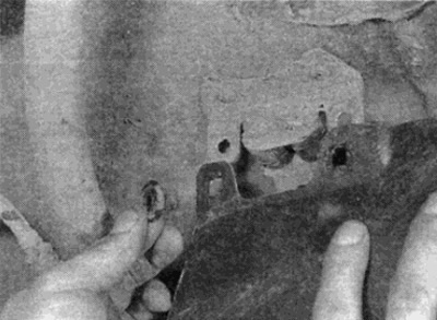
Fig. 4.5, a. Unfasten the fasteners...


Fig. 4.5, b....and remove the shield from the fuel pump, filter and battery
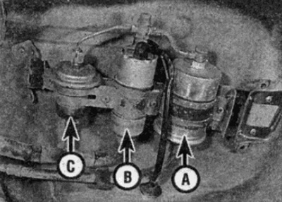
Fig. 4.5, b....and remove the shield from the fuel pump, filter and battery


Fig. 4.5, c. Gasoline filter (A), pump (B) and battery (C)

Fig. 4.5, c. Gasoline filter (A), pump (B) and battery (C)


6. Disconnect the fuel pump wire connectors from the connector block (see fig. 4.6). Label each connector well to avoid confusion during installation.
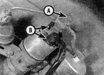


Fig. 4.6. Bypass bolt (A) and electrical connectors (B)

Fig. 4.6. Bypass bolt (A) and electrical connectors (B)


7. Using suitable hose clamps, clamp the flexible fuel supply hose to the fuel pump and the inlet pipe from the filter. Do not use a vice as this may cause internal damage to the hoses.

Warning: Do not pinch the hose at a bend, as this may cause it to deteriorate, resulting in fuel leaks. Only pinch the hoses at straight sections.


Homemade device

If you don't have hose clamps, fit two 13mm sockets on top of the jaws of a pair of vices and use them to squeeze the hose. The round surfaces of the sockets will protect the hose from being crushed.

8. Loosen the nipples and disconnect the fuel lines from the rear of the fuel pump. Where bypass bolts are used, remove the sealing washers and destroy them - new ones are required when installing. Be prepared for some gasoline to spill - place a container under the pump and cover the surrounding surfaces with rags.

9. Loosen and remove the screws, loosen the mounting belt and remove the pump from the support bracket (see fig. 4.9).
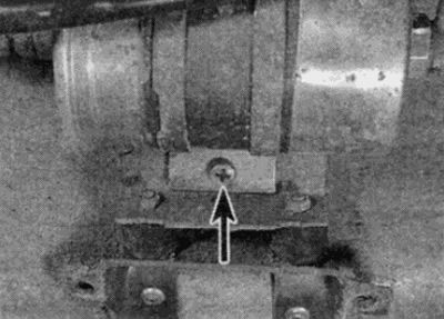
Fig. 4.9. To loosen the filter mounting clamp, unscrew the screws

Fig. 4.9. To loosen the filter mounting clamp, unscrew the screws


10. If the mounting bracket cannot be lowered sufficiently to remove the pump, where provided, remove the bypass bolts and disconnect the fuel line from the pump accumulator and filter. Again, be prepared for some fuel to spill and remove the sealing washers. Once the fuel line is disconnected, the fuel pump will be able to be lowered.


Installation


11. Installation is carried out in reverse order. Please note the following points:
  • a) Where provided, check that the anti-corrosion plastic gasket is installed correctly to prevent metal-to-metal contact between the pump and the clamp.
  • b) When connecting the bypass bolts, install new sealing washers.

12. When finished, start the engine and check that there are no leaks around the removed parts. Note that air has entered the fuel system and it may take longer than usual for the engine to start.
This article is available at: russian, bulgarian, belarusian, ukrainian, serbian, croatian, romanian, polish, slovak, hungarian
The article has been verified: Lukyanov Nikita Ilyich
Share with friends:
◀ Previous
C-Class 190 (W201) / Injection system (gasoline)
Next ▶

Air cleaner and filter element — removal and installation
Fuel injection system — leak
Basic information and precautions
Technical data
Fuel level indicator sensor — removal and installation
Gas tank — removal and installation
Throttle Cable — Removal, Installation and Adjustment
Fuel accumulator — removal and installation
Throttle body — removal and installation
More similar articles for repairing other models

☛ Fuel injection pump — removal and installation Mercedes W168 (1997-2004)
☛ Removal and installation the fuel pump Mercedes W123 (1976-1985)
☛ Removal and installation the fuel pump Mercedes W463 (1999-2019)
☛ Removal and installation the fuel pump assembly with fuel level sensor Mercedes W163 (1997-2005)
☛ Removal and installation the high pressure fuel pump (OM603) Mercedes W140 (1991-1998)
☛ Removal and installation of fuel injection pump Mercedes Sprinter (1995-2000, diesel)
Link in different formats to this article
Comments and feedback from visitors
No comments yet


How much will 42 + 22 ?


W203 (2000-2007) 
  • General information
  • Introduction to guide
  • User manual
  • Maintenance
  • Power unit
  • Gasoline engines
  • Diesel engines
  • Cooling system
  • Ventilation and heating
  • Supply system
  • Injection system (gasoline)
  • Injection system (diesel)
  • Exhaust system
  • Ignition and control system
  • Charge and launch systems
  • Transmission
  • Mechanical gearbox
  • Automatic gearbox
  • Clutch and drive shafts
  • Differential
  • Chassis
  • Brake system
  • Car suspension
  • Steering
  • Body
  • Exterior (external elements)
  • Interior (internal elements)
  • Electrical equipment
  • Equipment and devices
  • Lighting system
  • Electrical diagrams (2000)
  • Electrical diagrams (since 2001)
W202 (1993-2000) 
  • General information
  • User manual
  • Driving a car
  • Car care
  • Maintenance
  • Power unit
  • Gasoline engines
  • Diesel engines
  • Lubrication system
  • Cooling system
  • Heating and ventilation
  • Ignition system
  • Fuel system
  • Injection system (gasoline)
  • Injection system (diesel)
  • Exhaust system
  • Transmission
  • Clutch
  • Car gearbox
  • Chassis
  • Suspension, wheels and tires
  • Steering
  • Brake system
  • Body
  • Exterior (external elements)
  • Interior (internal elements)
  • Doors and windows
  • Electrical equipment
  • Equipment and devices
  • Power devices
  • Lighting system
  • Electrical circuits
190 (W201) (1982-1993) 
  • General information
  • Introduction to the guide
  • Operation and care
  • Maintenance (gasoline)
  • Maintenance (diesel)
  • Troubleshooting
  • Power unit
  • Petrol engine I4
  • Petrol engine V6
  • Diesel engines
  • Engine overhaul
  • Cooling and heating
  • Power system (carburetor)
  • Injection system (gasoline)
  • Injection system (diesel)
  • Exhaust system
  • Charge and start system
  • Ignition system (I4)
  • Ignition system (V6)
  • Diesel heating system
  • Transmission
  • Clutch
  • Mechanical gearbox
  • Automatic gearbox
  • Cardan shaft and axle shafts
  • Chassis
  • Brake system
  • Car suspension
  • Steering
  • Body
  • Exterior (external elements)
  • Interior (internal elements)
  • Doors, locks and windows
  • Electrical equipment
  • Equipment and devices
  • Electrical circuits
 
MercedesMan.ru © 2017–2026 · Mobile version · Read about Mercedes · Sitemap: EN BG BY UA RS HR RO PL SK HU · Feedback · Site search · Bookmark A-Class (W168) · C-Class (W201) · C-Class (W202) · C-Class (W203) · E-Class (W123) · E-Class (W124) · E-Class (W210) · G-Class (W463) · M-Class (W163) · S-Class (W116, petrol) · S-Class (W126, petrol) · S-Class (W140) · S-Class (W220) · Sprinter · Vito 1 · Vito 2 · Vario 814D ·
 
We only use cookies without which some of the site's features may not be available.