
Cars BMW Cars Volkswagen Cars Chevrolet Cars Land Rover Cars Lada Cars Honda Cars Peugeot
English Русский
Български
Беларускі
Український
Српски
Hrvatski
Română
Polski
Slovenský
Magyar
Bookmark News and articles Sitemap Feedback Site search
MercedesMan.ru


A-Class C-Class E-Class G-Class M-Class S-Class Others
Sprinter (1995-2000, diesel) Vito 1 (1996-2003) Vito 2 (2003-2014, diesel) Vario 814D (1996-2003, diesel)
  • Main
  • Mercedes-Benz
  • Sprinter (1995-2000)
  • Power unit
  • Power and exhaust system
  • Removal and installation of fuel injection pump

Removal and installation of fuel injection pump (Mercedes-Benz Sprinter 903)

0
To install the fuel injection pump, a special tool is required. It must be prepared before removing the pump. In addition, you will need a wrench with a 27 mm head to turn the crankshaft, a 14 mm open-end wrench with a sawn slot to unscrew the fuel injection system lines and a special wrench to turn the high-pressure fuel pump shaft.

Removal and installation of the fuel injection pump is carried out as follows:
  • remove the negative terminal from the battery;
  • clear access to system components from the front of the vehicle;
  • remove the radiator;
  • remove vacuum pump;
  • remove the dipstick guide tube;
  • remove the oil filter element and the filter itself with the oil cooler (the works are described in the relevant section). Pour the oil into a container;
  • turn the crankshaft in the direction of rotation until the piston of the first cylinder in the compression phase reaches the 15° mark after TDC (according to the pointer on the camshaft drive mechanism cover and the mark on the crankshaft pulley);
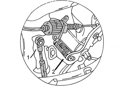
Figure 150. Disconnecting the rod (1) from the regulator lever (2)

Figure 150. Disconnecting the rod (1) from the regulator lever (2)

  • disconnect the fuel pedal drive from the regulator lever (figure 150);
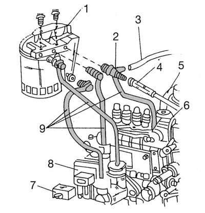
Figure 151. Fuel filter: 1 - fuel filter holder; 2 - connecting nipple; 3 - straight pipeline; 4 -…

Figure 151. Fuel filter: 1 - fuel filter holder; 2 - connecting nipple; 3 - straight pipeline; 4 - return pipeline; 5 - vacuum hose; 6 - vacuum regulator mechanism; 7 — electronic shut-off valve plug connector; 8 - electronic shut-off valve; 9 — fuel lines


  • first disconnect the fuel lines 9 (figure 151) from the fuel filter. At the same time, do not allow fuel to leak. The sealing rings located under the connections must always be replaced. Then disconnect the direct 3 and return 4 pipelines from the connecting nipple 2;
  • disconnect vacuum hose 5 from diaphragm mechanism 6 of fuel pressure regulator;
  • disconnect the plug connector 7 of the electronic shut-off valve 8;
  • do not bend the fuel injection system lines when disconnecting;
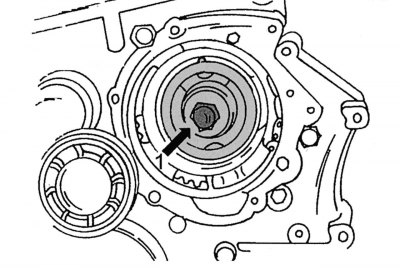
Figure 152. Injection advance clutch
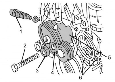
Figure 152. Injection advance clutch


Figure 153. Dismantling the fuel injection pump (parts removed during dismantling): 1 - chain…

Figure 153. Dismantling the fuel injection pump (parts removed during dismantling): 1 - chain tensioner; 2 - central bolt; 3 - washer; 4 - spring washer; 5 - centering sleeve; 6 — pump mounting bolts


  • unscrew bolt 1 in the center of the injection advance coupling (figure 152). In this case, the crankshaft should be blocked from turning. Note: The bolt has a left-hand thread. There are a regular and spring washers under the bolt (figure 153);
  • remove chain tensioner 1 (figure 153) (see section 2 "Engine");
  • unscrew the pump mounting bolts 6 and remove the square nuts from the back side. Do not remove the top bolt;
  • remove the pump back, disconnecting the fuel pedal drive from the pump regulator lever;
  • when installing the pump, proceed as follows (adjustment of the fuel injection start moment is carried out only at a service station);
  • check that the position of the piston of the first cylinder of the engine still corresponds to the mark 15° after TDC. Otherwise, turn the crankshaft with the head of the wrench until the specified division coincides with the mark on the cover of the camshaft drive mechanism;
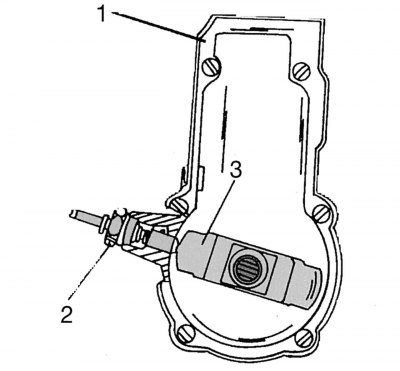
Figure 154. Fixing the fuel injection pump regulator: 1 — Fuel injection pump; 2 - lock bolt; 3 -…

Figure 154. Fixing the fuel injection pump regulator: 1 — Fuel injection pump; 2 - lock bolt; 3 - regulator with a protrusion

  • unscrew the plug on the side of the pump. Turn the pump shaft using the special key 601 589 00 08 00 until the regulator protrusion appears in the open hole. Screw the locking bolt 601 589 05 21 00 into the hole and tighten until you feel that the bolt has entered the protrusion of the regulator. Figure 154 shows the internal structure of the pump and the fastening of the regulator with a locking bolt;

Caution! The fuel injection pump can be easily damaged. After installing and securing the pump, the lock bolt should be unscrewed.


  • now you can start installing the pump:
  • tighten the pump flange mounting bolts to a torque of 20–25 N·m. Loosen the lock bolt and screw the plug into the hole to a torque of 30–35 N·m;
  • connect the fuel lines one by one. Before tightening the fastening nuts, carefully "tighten" them along the threads. Tightening torque 10–20 Nm;
  • tighten the central bolt of the injection advance coupling to a torque of 45 Nm, placing both washers under it (see above).

Further work is carried out in the reverse order of disassembly.
This article is available at: russian, bulgarian, belarusian, ukrainian, serbian, croatian, romanian, polish, slovak, hungarian
The article has been verified: Levin Kirill Glebovich
Share with friends:
◀ Previous
Mercedes Sprinter / Power and exhaust system
Next ▶

Precautions when working with the injection system
General description of the diesel fuel injection system
Checking the injection start timing
Injectors and injector bodies — troubleshooting
Removal and installation injectors
Repair and cleaning of injectors
Removal and installation the mixing chamber
More similar articles for repairing other models

☛ Fuel injection pump — removal and installation Mercedes W168 (1997-2004)
☛ Injection timing control device and high pressure fuel pump sprocket Mercedes 190 (W201) (1982-1993)
☛ Scheme 8. Diesel engine injection system with high-pressure fuel pump… Mercedes W210 (1996-2002)
☛ Removal and installation the fuel pump Mercedes W463 (1999-2019)
☛ Removal and installation the fuel pump assembly with fuel level sensor Mercedes W163 (1997-2005)
☛ Fuel injection and fuel supply system of a gasoline engine — general… Mercedes W140 (1991-1998)
Link in different formats to this article
Comments and feedback from visitors
No comments yet


How much will 20 + 49 ?


Vario 814D (1996-2003, diesel) 
  • General information
  • Maintenance
  • Power unit
  • Engines 602.984/985
  • Engines 904.908/914/923/936
  • Transmission
  • Clutch
  • Manual gearbox 711.613
  • Manual gearbox 710.64/66
  • Manual gearbox 715.051
  • Automatic gearbox 723.345
  • Power take-off box
  • Chassis
  • Front suspension
  • Rear suspension
  • Steering
  • Brake system
  • Body and electrical equipment
  • Interior (internal elements)
  • Exterior (external elements)
  • Heater and air conditioner
  • Electrical diagrams
Vito 2 (2003-2014, diesel) 
  • General information
  • User manual
  • Maintenance
  • Diesel engine OM646
  • Engine repair
  • Cooling and lubrication system
  • Power and exhaust system
  • Transmission
  • Clutch
  • Car gearbox
  • Chassis
  • Front suspension
  • Rear suspension
  • Steering
  • Brake system
  • Body
  • Body elements
  • Electrical equipment
  • Equipment and devices
  • Security systems
  • Electrical circuits
Vito 1 (1996-2003) 
  • General information
  • User manual
  • Maintenance
  • Petrol engines 2.0 l
  • Engine repair
  • Lubrication system
  • Cooling system
  • Power and control system
  • Petrol engines 2.8 l
  • Engine repair
  • Lubrication system
  • Cooling system
  • Power and control system
  • Diesel engines 2.3 l
  • Engine repair
  • Cooling system
  • Lubrication system
  • Turbocharging and recycling
  • Power and control system
  • Diesel engines 2.2 l
  • Engine repair
  • Cooling system
  • Lubrication system
  • Turbocharging and recycling
  • Power and control system
  • Transmission
  • Clutch
  • Mechanical gearbox
  • Automatic gearbox
  • Chassis
  • Front suspension and wheels
  • Rear suspension
  • Steering
  • Brake system
  • Body
  • Exterior (external elements)
  • Interior (internal elements)
  • Electrical equipment
  • Equipment and devices
  • Heater and air conditioner
  • Electrical circuits
Sprinter (1995-2000, diesel) 
  • General information
  • Introduction to the guide
  • Maintenance
  • Power unit
  • Engine repair
  • Lubrication system
  • Cooling system
  • Power and exhaust system
  • Transmission
  • Clutch
  • Mechanical gearbox
  • Automatic gearbox
  • Front axle
  • Rear axle and cardan
  • Chassis
  • Car suspension
  • Steering
  • Brake system
  • Tires and wheels
  • Electrical equipment
  • Equipment and devices
  • Headlights and lighting
  • Power devices
  • Electrical circuits
 
MercedesMan.ru © 2017–2026 · Mobile version · Read about Mercedes · Sitemap: EN BG BY UA RS HR RO PL SK HU · Feedback · Site search · Bookmark A-Class (W168) · C-Class (W201) · C-Class (W202) · C-Class (W203) · E-Class (W123) · E-Class (W124) · E-Class (W210) · G-Class (W463) · M-Class (W163) · S-Class (W116, petrol) · S-Class (W126, petrol) · S-Class (W140) · S-Class (W220) · Sprinter · Vito 1 · Vito 2 · Vario 814D ·
 
We only use cookies without which some of the site's features may not be available.