
Removing
Attention: In order to perform the removal of the device and sprocket described below, the injection pump shaft must be fixed using a tool of a special configuration. It is too difficult to manufacture such a device with the required accuracy on your own and, if used, can lead to internal damage to the fuel pump. Therefore, it is recommended to rent this tool from a Mersedes-Benz dealer or a Bosch diesel power system specialist.
1. Disconnect the negative battery terminal
2. If required, remove the lower motor protection.
3. Remove the accessory drive belt in the following order.
- A) Remove the plastic plug, unscrew the fastening bolt and remove the auxiliary drive belt idler pulley.
- b) Loosen the mounting bolt and remove the radiator fan pulley.
- V) Loosen the bolts and remove the tensioner damper spacer. Remove all spacers and/or brackets from the bolts, noting their location.
- G) Using pliers, unhook the tension spring, noting its correct location, to restore it to assembly.
- d) If required, remove the plug and, having unscrewed the tensioner mounting bolt, pull out the bushing on which the tensioner is mounted.
- e) Remove the tensioner and remove the gasket (if provided).
4. In accordance with chapter 3, remove the radiator fan and its casing.
5. In accordance with Chapter 9, remove the vacuum brake booster pump from under the camshaft drive chain cover. Please note that the gasket must be replaced during installation.
6. Using a socket or wrench, use the pulley/damper to hub bolt to turn the crankshaft in the direction of its normal rotation by 15°after piston No. 1 reaches TDC. Use the pointer on the timing chain cover and the scale on the damper to determine the correct position (refer to fig. 7.9).
7. If necessary, unscrew the bolts and remove the housing holding the sprocket in front of the fuel pump sprocket, (see fig. 8.7) On later models, the housing is held in place by a dowel pin. Remove the pin by screwing an M6 bolt into its end. Then, place a sliding hammer or impact puller on the head of the bolt, gradually remove the pin.
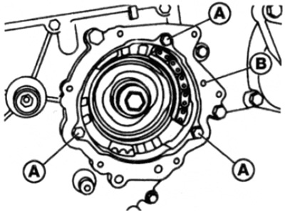
Pic. 8.7. sprocket housing
A Mounting bolts
The pin
8. Refer to chapter 2B and do the following:
- A) Remove the cylinder head cover.
- b) Remove the camshaft timing chain tensioner.
- V) Loosen and remove the camshaft sprocket mounting bolt and washer.
9. Fix the relative position of the camshaft sprocket and the drive chain by tightly pulling them together with a nylon cable tie for tying the cables into bundles or something similar.
10. Move the sprocket with the chain attached to it off the end of the camshaft and leave it inside the camshaft timing chain cover.
11. If not already done, remove the fuel pump sprocket retaining housing.
12 Lock the crankshaft by holding it with a socket or wrench on the pulley/damper-to-hub bolt, then loosen and remove the fuel pump sprocket center bolt.
Note: This bolt has a left hand thread. Remove the puck.
13. Using a socket or wrench, turn the crankshaft in the direction of its normal rotation by using the bolt securing the pulley / damper to the hub 15 degrees after the No. 1 piston reaches TDC. Use the pointer on the timing chain cover and the scale on the damper to determine the correct position (see fig. 7.8).
14. Apply paint marks on the relative position of the chain and sprocket of the fuel pump - when installed, they will serve as alignment marks.
15. After that, in order to remove the chain and sprocket, it is necessary to remove the chain from the sprocket teeth. To do this, make a fixture from a piece of thin metal: cut a rectangle approximately 140x70 mm in size and bend it along a radius approximately equal to the radius of the fuel pump sprocket.
16. Insert this homemade tool in front of the fuel pump sprocket, then unclench it so that it will push the chain off the sprocket teeth and leave it in this position (see fig. 8.16).
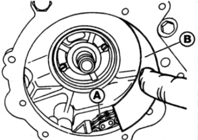
Pic. 8. 16. Unclench the homemade fixture so as to separate the chain from the teeth of the star
A drive chain
The Homemade Fixture
17. Separating the sprocket teeth from the chain, remove the timing device along with the sprocket from the camshaft drive chain housing, using large pliers or clamps for this.
18. Unscrew and remove the plug on the side of the fuel pump. Be prepared for possible fuel leakage and lay a piece of rag that absorbs fuel well near the plug hole.
19. Using suitable grips, turn the fuel pump shaft in the normal direction of rotation while observing the movement of the regulator rotor through the plug hole. Continue turning the shaft until the tab on the rotor lines up with the hole. In this position, the rotor must be fixed relative to the pump housing with a special device from Mercedes-Benz (read the note at the beginning of this paragraph) (see fig. 7.24). This step should not be neglected, as this is the only way to ensure that the injection pump injection timing is correctly set during assembly.
Caution: Be careful not to damage the surface of the pump shaft when gripping the jaws.
Installation
20. Installation is carried out in the reverse order of removal, taking into account the following points:
- A) Before installing the sprocket and the injection timing device on the pump shaft, make sure that the crankshaft has not moved from the position corresponding to 15°after the No. 4 piston reaches TDC.
- b) Use the alignment marks made when removing the target to align the target and the fuel pump drive sprocket.
- V) Stop the crankshaft and tighten the fuel pump sprocket bolt to the required torque, taking into account that the bolt has a left-hand thread.
- G) Before. how to rotate the crankshaft, remove the fixing tool from the hole of the injection timing device of the pump (and install the cap).
- d) Talk to chapter 2B and install the camshaft sprocket. In order to make sure that the installation is correct, make one complete revolution of the crankshaft and check that the TDC alignment marks on the crankshaft and camshaft are correctly aligned.
- e) If the brake vacuum pump has been removed, a new seal must be used when installing it - refer to chapter 9.
- and) Upon completion, check and, if necessary, adjust the moment of fuel supply by the high pressure fuel pump, in accordance with paragraph 9.
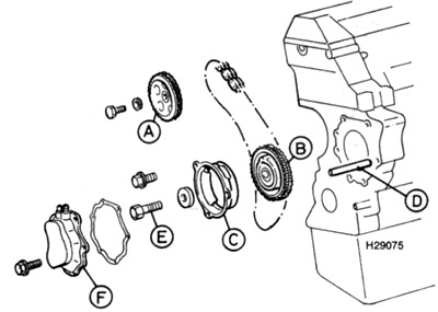
Pic. 8.20. Injection pump sprocket and injection timing device (timing)
A Camshaft sprocket
The injection pump sprocket and timing device
C Clip
D Pin
E Sprocket bolt
F Vacuum pump