



Contents: Removal ↡ Installation ↡
Removal
Turbocharged base engines
1. Disconnect the negative battery terminal
2. To provide easy access, remove the air cleaner assembly as described in paragraph 2. Where required, also unscrew the fuel line brackets from the intake manifold (see fig. 16.2).
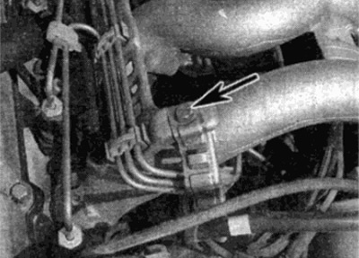
Fig. 16.2. Unscrew the fuel line brackets (shown by arrow) from the intake manifold
3. Disconnect the ventilation hoses from the fittings on top of the manifold sleeves (see fig. 16.3).
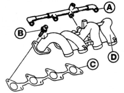
Fig. 16.3. Intake manifold design - non-turbocharged engines
A Ventilation hose
Intake Manifold Mounting Bolts
With Gasket
D Collector body
4. Working in sequence, loosen the manifold mounting bolts until they can be removed by hand.
5. Lift the manifold up over the cylinder head and remove the gasket.
Turbocharged engines
6. Disconnect the negative battery terminal.
7. Disconnect the vacuum hose from the fitting at the end of the high pressure chamber (see fig. 16.7).
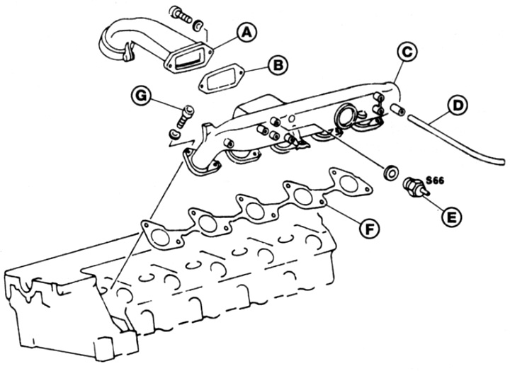
Fig. 16.7 Intake manifold design - turbocharged engines
A Input channel
In Gasket
With Camera Body
D Vacuum hose
E Pressure switch
F Gasket
G Manifold to cylinder head mounting bolts
8. Disconnect the engine overload protection pressure sensor wires from the connector.
9. Unbolt the intake manifold section on the support bracket on top of the cylinder head. Remove the bolts and disconnect the manifold from the intake manifold. Remove the gasket.
10. Loosen the mounting bolts one by one until they can be removed by hand.
11. Lift the manifold up over the cylinder head and remove the gasket.
Installation
12. Installation is performed in the reverse order of removal. Tighten the intake manifold mounting bolts to the required torque.