
Crankshaft speed sensor
Removing
1. Disconnect the negative battery terminal.
2. Disconnect the crankshaft sensor wires from the harness at the connector located in the engine compartment behind the battery.
3. The sensor is located on the mating surface between the cylinder block and the gearbox bell housing above the starter opening. Loosen and remove the bolt, then remove the sensor from the gearbox housing. If present, remove the gasket.
Installation
4. Install the crankshaft sensor in the reverse order of removal. Before screwing it into the gearbox housing, make sure that the bushing (if provided) installed on the sensor probe.
Coolant temperature sensor
Removing
5. Refer to chapter 1 and partially drain the cooling system. Make sure the startup key is turned off.
6. The coolant temperature sensor is screwed into the upper wall of the cylinder head on the left side of the engine. Do not confuse it with the temperature gauge sensor.
7. Disconnect the sensor wire from the connector.
8. Turn out the gauge from a head of cylinders and remove a sealing ring.
Installation
9. Installation is made in an order the return to an order of removal. When finished, add fluid to the cooling system.
Electronic control unit
Removing
10. Electronic system control unit (ELR) located in the rear of the engine compartment behind a false panel.
11. Disconnect the negative battery terminal
12. Disconnect the control box wires from the multi-pin connector.
13. Turn away screws of fastening and remove the block from a partition.
Installation
14. Installation is made in an order, the return to an order of removal.
Electromagnetic drive
Removing
15. Electromagnetic drive of the idle control system (ELR) bolted to the rear of the injection pump housing. If the vehicle is equipped with both electronic idle control (ELR). and anti-jerk system (ARA), then the upper of the two drives will be the electromagnetic drive ELR (see fig. 12.15).
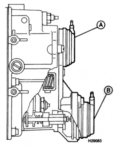
Pic. 12.15. Rear of high pressure fuel pump (side view)
And the electromagnetic drive of the ELR system
In the electromagnetic drive of the ARA system
16. Disconnect the negative battery terminal.
17. On non-turbo engines, refer to paragraph 2 and remove the air cleaner assembly.
18. Disconnect the drive wires at the connector.
19. Loosen and remove the two screws on the back of the drive. Remove the appropriate brackets.
20. Remove drive housing, o-ring, shim and spacer plate (if provided).
Installation
21. Installation is made in an order, the return to an order of removal. Consider the following points.
- A) Transfer the shims to the new drive if the block is to be replaced with a new one.
- b) Replace O-ring.
- V) Make sure the electrical connector is facing up after installing the drive.