
Removing
Attention: To carry out the operation described below, the injection pump shaft must be fixed using a special tool with a special configuration. It is too difficult to manufacture such a device with the required accuracy on your own and, if used, can lead to internal damage to the fuel pump. Therefore, it is recommended to rent this tool from a Mersedes-Benz dealer or a Bosch diesel power system specialist.
1. Disconnect the negative battery terminal.
2. If required, remove the lower motor protection.
3. Remove the accessory drive belt in the following order.
- A) Remove the plastic plug, unscrew the fastening bolt and remove the auxiliary drive belt idler pulley.
- b) Loosen the mounting bolt and remove the fan pulley.
- V) Loosen the bolts and remove the tensioner damper spacer. Remove all spacers and/or brackets from the bolts, noting their location.
- G) Using pliers, unhook the tension spring, remembering its correct position in order to restore it during assembly.
- d) If required, remove the plug and, having unscrewed the tensioner mounting bolt, pull out the bushing on which the tensioner is mounted.
- e) Remove the tensioner and remove the gasket (if provided).
4. According to chapter 3 remove the fan and its shroud.
5. In accordance with Chapter 9, remove the vacuum brake booster pump from under the camshaft drive chain cover. Please note that the gasket must be replaced during installation.
6. If desired, access can be improved by removing the intake manifold as described in paragraph 16.
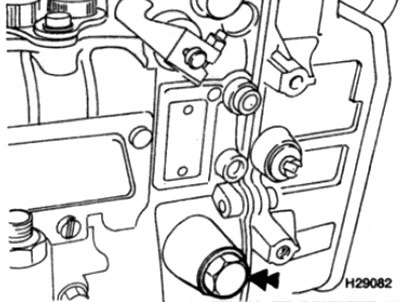
7. Stop the crankshaft by holding it with a socket or wrench on the pulley / damper-to-hub bolt, then loosen and remove the fuel pump sprocket center bolt (see fig. 7.7).
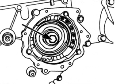
Pic. 7.7. Loosen and remove the injection pump sprocket center bolt (shown by arrow) - note that the bolt has a left-hand thread
Note: This bolt has a left hand thread. Remove the puck.
8. Using a socket or wrench, use the pulley/damper-to-hub bolt to turn the crankshaft in the direction of its normal rotation by 15 degrees after piston No. 1 reaches TDC. Use the pointer on the timing chain cover and the scale on the damper to determine the correct position (see fig. 7.8).
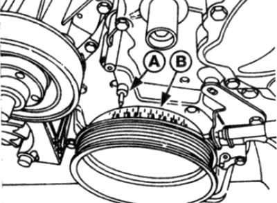
Pic. 7.8. Set the engine crankshaft to 15 degrees after TDC on cylinder #4 using the pointer on the camshaft timing chain cover and the graduated scale on the damper
A Pointer
B Graduated scale
9. Contact chapter 2B and remove the camshaft timing chain tensioner (see fig. 7.9).
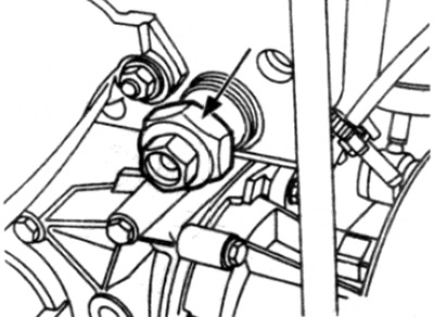
Pic. 7.9. Remove the camshaft timing chain tensioner (shown by arrow)
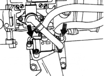
10. Using an appropriate wrench, unscrew the fittings and disconnect the high pressure fuel line from the injection pump. To avoid fuel spillage, lay a highly absorbent wiping material underneath (see fig. 7.10).
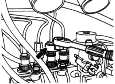
Pic. 7.10. Unscrew the fittings and disconnect the high pressure fuel line from the injection pump
11. Similarly, loosen and remove the bypass bolts, then disconnect the inlet, feed and outlet hoses from the high pressure fuel pump. Remove the gaskets and dispose of them - new ones must be used for installation. Clamp the flexible sections of the hoses to avoid fuel spillage later on.
12. If provided, remove the high pressure fuel pump control lever damper.
13. Disconnect all vacuum hoses from the actuators at the top and rear of the injection pump, remembering their location in order to reinstall them correctly.
14. Similarly, disconnect all electrical wires from the actuators at the top and rear of the high pressure fuel pump, remembering the location of the connectors in order to reconnect them during installation.
15. Disconnect the accelerator linkage from the high pressure fuel pump control lever.
16. Mark the fuel pump housing. to indicate its position relative to the back of the support flange to allow for approximate alignment during installation.
17. When the fuel pump is removed, the sprocket (and sync device) must be held stationary inside the camshaft drive chain housing so that it cannot disengage from the chain, but in such a way that it can turn when turning the crankshaft by hand. On the latest models, a special holding case is installed for this purpose.
18. On early models not equipped with such a housing, you must have a piece of metal pipe at the ready of approximately the same diameter as the threaded section of the central bolt of the sprocket.
19. Unscrew and remove the bolts that secure the front of the injection pump to the support flange, (see fig. 7.19). Remove the bolt that secures the back of the pump to the support bracket and remove the fuel pump. Hold the pump sprocket in place at the same time (and sync device).
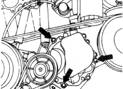
Pic. 7.19. Loosen and remove bolts (indicated by arrows), that hold the front of the injection pump on the support flange
Attention: do not allow the sprocket and chain to separate. Be prepared for the fact that when the pump is removed from the flange, some engine oil will leak out.
20. If the sprocket retainer housing is not installed on early models, insert a piece of pipe into the center hole of the sprocket. Pass a piece of strong wire or a thick nylon tie through the pipe section to bundle the cables into bundles, then secure the sprocket to the top of the camshaft timing chain case with it.
21. Remove the bolts and remove the fuel thermostat from the high pressure fuel pump housing and remove it from the working area (see fig. 7.21). It is not necessary to disconnect the thermostat from the fuel lines.
Pic. 7.21. Turn away bolts (shown by arrows) and disconnect the fuel thermostat from the high pressure fuel pump housing
22. Seal all open fuel line connections to reduce fuel loss and prevent dirt from entering (see homemade tool).
Pull a piece of hose over the bypass bolt to cover the holes, then screw the bolt into place in the fuel pump and tighten it by hand.
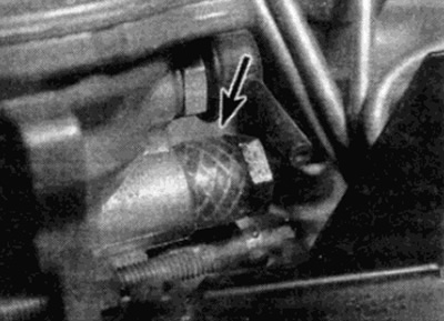
23. Clamping the fuel pump in a vise, unscrew and remove the plug on the side of the pump housing (see fig. 7.23).
Pic. 7.23. Unscrew and remove the cap (shown by arrow) on the side of the pump housing
24. Using pliers, turn the fuel pump shaft in the normal direction, observing the movement of the regulator rotor through the plug hole. Continue turning the axle until the tab on the adjuster lines up with the hole. In this position, the rotor must be fixed relative to the pump housing with a special device from Mercedes-Benz (read the note at the beginning of this paragraph) (see fig. 7.24).
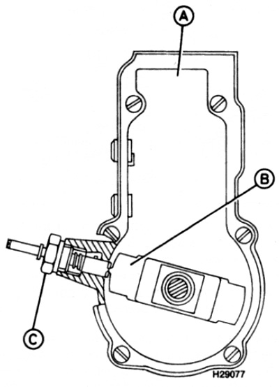
Pic. 7.24. Rotate the fuel pump shaft until the tab on the regulator rotor is aligned with the inspection hole
A Pump under test - rear view
The Rotor Regulator
C Fixing device
Caution: Be careful not to damage the surface of the pump shaft when clamping with the jaws.
25. Remove the o-ring and discard it - a new one must be used for installation.
Installation
26. Installation is carried out in the reverse order of removal, taking into account the following points:
- A) Install the O-ring to the fuel pump after lightly lubricating it with engine oil.
- b) Make sure that the crankshaft has not precisely moved out of its 15°position after piston #1 reaches TDC.
- V) Stop the crankshaft and tighten the fuel pump sprocket bolt to the required torque, given that the bolt has a left-hand thread.
- G) Before turning the crankshaft, remove the fuel pump retainer and install the plug.
- d) Tighten the fuel pump mounting bolts to the required torque.
- e) Connect the high pressure fuel lines and tighten all connections securely.
- and) New sealing washers must be installed on the bolts of the supply, supply and return fuel lines.
- h) If the vacuum pump has been removed, a new seal must be used when installing it - refer to chapter 9.
- And) Upon completion, check and, if necessary, adjust the fuel supply by the fuel pump, in accordance with paragraph 9.