
Removing
1. Remove the radiator, vacuum pump, oil gauge guide tube, oil filter, oil filter housing with oil cooler.
2. Set the piston of the first cylinder to position 15°after BDC.
3. Disconnect the connecting rod 1 from the control lever of the injection pump rail 2 (see fig.4.63).
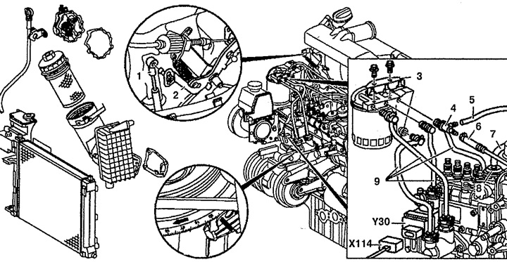
Pic. 4.63. High pressure fuel pump:
1. Connecting lever,
2. Lever control rail injection pump,
3. Bracket,
4. Tee,
5. Fuel injection line,
6. Drain fuel line,
7. Vacuum tube,
8. Stop vacuum unit,
9. Fuel lines,
X114. immobilizer wiring connector,
Y30. Electronic blocking valve.
4. Disconnect the fuel lines 9 from the fuel filter, check the seals.
5. Disconnect the supply 5 and drain 6 fuel lines from the tee 4.
6. Disconnect the vacuum tube 7 from the stop vacuum unit 8.
7. Disconnect connector 32 (see fig.4.64).
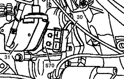
Pic. 4.64 a. High pressure fuel pump:
30, 32. Wiring connector,
31. Vacuum control valve,
S70. Microswitch.
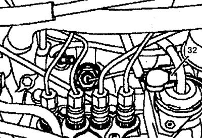
Pic. 4.64 b. High pressure fuel pump
8. Disconnect connector X114 from the RCD electronic blocking valve (only on cars with immobilizer).
9. Disconnect the fuel lines from the injection pump.
10. Disconnect the vacuum tube 18 from the compressed air supply unit 17 (see fig.4.65).
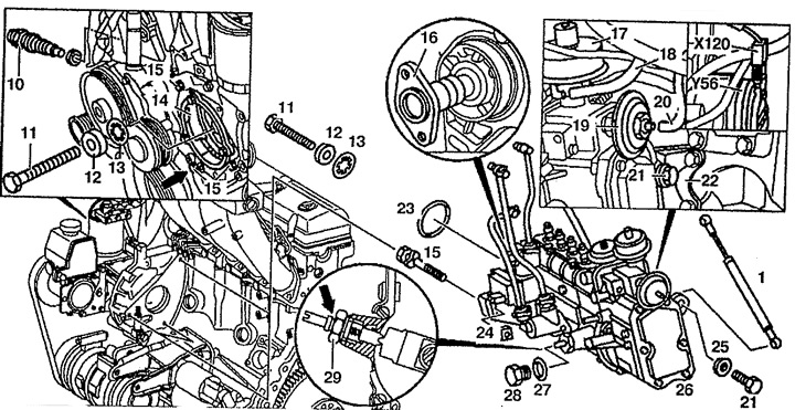
Pic. 4.65. High pressure fuel pump:
1. Connecting lever,
10. Chain tensioner,
11. Central bolt,
12, 25. Gasket,
13. Spring washer,
14. Centering sleeve,
15, 21. Bolt,
16. Key,
17. Air supply unit,
18, 20. Vacuum tube,
19. Vacuum assembly of the PISI system,
22. Bracket,
23, 27. Oil seal,
24. Square nut,
26. High pressure fuel pump,
28. Cork,
29. Locking bolt,
X120. Idler wiring harness connector,
Y56. Idle drive solenoid valve.
11. Disconnect vacuum tube 20 from vacuum assembly 19 PISI (only on engines with PISI system).
12. Disconnect the X120 wiring connector from the idle speed control solenoid valve Y56 (only on engines with electronic idle speed control).
13. Unscrew bolt 21 from bracket 22.
14. Install the centering sleeve 14.
15. Unscrew the central bolt 11 and remove it together with the gasket 12 and spring washer 13.
16. Remove the chain tensioner 10.
17. Unscrew the bolt 15 fastening the injection pump to the flange and remove it together with square nuts 24. The lower bolt 15 cannot be removed (arrow), and the upper one can be removed only by lifting the engine.
18. Remove injection pump 26.
19. Disconnect the connecting rod 1 from the injection pump rail.
20. Disconnect the fuel lines from the injection pump.
Installation
21. Connect the fuel lines to the injection pump. Check seals, replace if necessary.
22. Block high pressure fuel pump 26 before installation using bolt 29, observing the distance (arrow) between nut and bolt.
23. Check up installation of the piston of the first cylinder in position 15°after BDC.
24. Install high pressure fuel pump 26 and screw it to the flange. Replace oil seal 23 and lubricate it with oil before installation.
25. Remove blocking bolt 29 and tighten plug 28. Replace oil seal 27.
26. Install the timing chain tensioner 10.
27. Tighten center bolt 11 with gasket 12 and spring washer 13.
28. Remove the centering sleeve 14.
29. Install connecting rod 1.
30. Attach the remaining elements removed from the engine. The injection system bleeds automatically.
31. Check the start of the fuel supply.
32. Check up turns of idling and, if necessary, adjust them.