



Contents: Removal ↡ Installation ↡
Removal
1. Disconnect the connecting pipe 5 between the compressed air supply pipe 4 and the mixing chamber 1 (see figure 4.59).
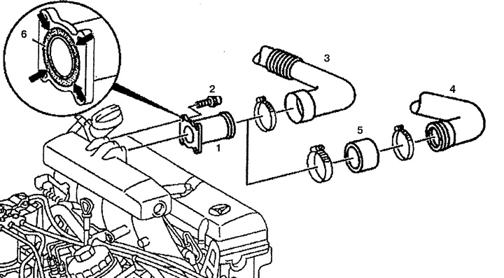
Figure 4.59. Mixing chamber:
1. Mixing chamber,
2. Bolt,
3. Air intake pipe (only on 601.942),
4. Compressed air supply tube (only on 601.970),
5. Connecting tube,
6. Stopper.
2. Remove the mixing chamber 1.
Installation
3. Installation is carried out in the reverse order of removal. Replace stopper 6, paying attention to its correct installation (arrows).