
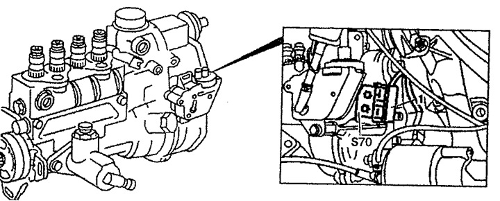
Pic. 4.66. High pressure fuel pump microswitch:
1. Wiring connector,
S70. High pressure fuel pump microswitch.
Microswitch adjustment
2. Remove the bracket for fastening the injection pump to the cylinder block.
3. Set the shim 8c to position E (installation) on bolt 8f injection pump (see fig. 4.67). Bolt 8f is located at the rear of the injection pump. Adjusting gasket (at which the microswitch is switched off in position 10 before full load) shown in fig. 4.68.
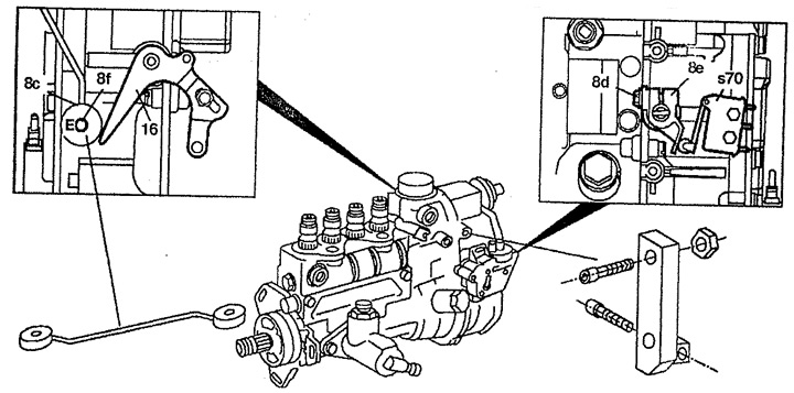
Pic. 4.67. Microswitch adjustment.
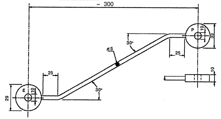
Pic. 4.68. Adjusting lining of the HPFP microswitch.
4. Attach the mounting device to the front of the injection pump. The installation device for installing the high pressure fuel pump microswitch is shown in fig. 4.69. To install it, insert bolt 1 with nut 2 into the through hole. Bolt 1 is designed to connect the device to the injection pump. Screw bolt 3 into threaded hole M5. Bolt 3 is for fine adjustment of the trailing arm.
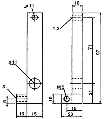
Pic. 4.69. Setting device for installing the high pressure fuel pump microswitch:
1. Bolt M45x45,
2. Nut M5,
3. Bolt M5x30.
5. Loosen bolt 8d.
6. Press the lever 16 for controlling the injection pump rail as far as it will go and lock it in this position.
7. Turn the trailing arm 8e until both switch-off points (two clicks) microswitch will not be overcome. Adjust the position of the trailing arm by turning the adjuster cam bolt.
8. Loosen the injection pump rail control lever.
Examination
9. Set the shim 8c to position P (examination) on bolt 8f injection pump.
10. Press the lever 16 for controlling the injection pump rail as far as it will go and lock it in this position. If the setting is correct, only the first switch position point should be passed (one click). If necessary, repeat the adjustment.
11. Remove the setting device.
12. Install the injection pump mounting bracket.
- Injection pump trailing arm microswitch points: 10°and 15°