
Removing
Attention! To fix the fuel pump shaft in the installation position, it is necessary to use a special tool. Using a self-made tool may damage the internal parts of the fuel pump.
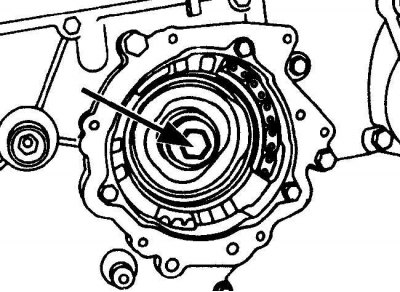
Arrangement of a bolt with the left carving of fastening of an asterisk of the fuel pump
Setting the piston of the first cylinder to position 15°
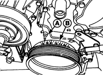
When installing the piston of the first cylinder in position 15°after TDC, align the corresponding mark on the pulley with the pointer.
A - pointer; B - marks on the pulley
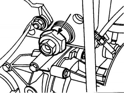
Location of drive chain tensioner
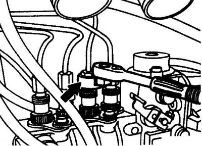
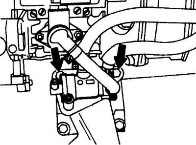
Unscrewing the fuel lines from the fuel pump
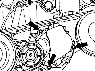
Arrangement of bolts of fastening of a forward part of the fuel pump to a fixing flange
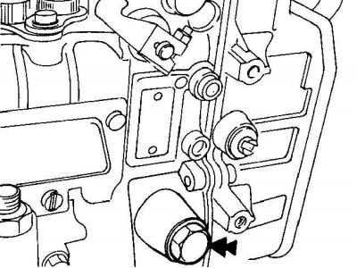
Location of the fuel thermostat mounting bolts
The location of the plug that closes the installation hole of the high pressure fuel pump
Using a special tool to secure the regulator housing from turning
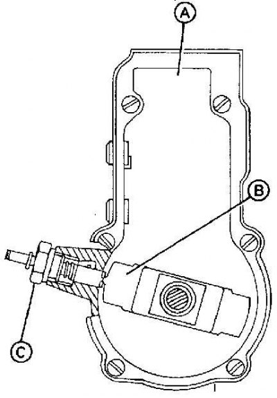
A - fuel pump (back view); B - regulator housing; C - special tool for fixing the regulator body
1. Remove the ground wire from the battery.
2. Remove the clips and mounting panel from the bottom of the engine compartment.
3. Remove the auxiliary drive belt tensioner.
4. Remove the radiator fan and shroud.
5. Remove the vacuum pump from the cylinder head cover. Remove the gasket from the vacuum pump.
6. Remove the intake manifold.
7. On 6-cylinder models with vehicle speed control, unscrew the actuator and move it to the side.
8. Secure the engine crankshaft from turning, then unscrew the central bolt of the fuel pump sprocket (see fig. Arrangement of a bolt with the left carving of fastening of an asterisk of the fuel pump).
Attention! The fuel pump sprocket bolt has a left-hand thread.
9. At the crankshaft pulley bolt, rotate the engine crankshaft in the working direction until the piston of the first cylinder is at 15°after top dead center. Install by aligning the corresponding mark on the crankshaft pulley with the pointer (see fig. Setting the piston of the first cylinder to position 15°).
10. Remove the drive chain tensioner (see fig. Location of drive chain tensioner).
11. Using the appropriate wrench, unscrew the fuel lines from the fuel pump to the fuel injectors (see fig. Unscrewing the fuel lines from the fuel pump).
12. Unscrew the connecting bolts and disconnect the supply and return fuel hoses from the fuel pump.
13. Label and disconnect the vacuum hoses from the actuators at the top and rear of the fuel pump.
14. Tag and disconnect the electrical connectors from the actuators and sensors on the top and rear of the fuel pump.
15. Disconnect the accelerator link from the fuel pump control lever.
16. Using a scriber, mark the position of the fuel pump in relation to the rear surface of the mounting flange.
17. After removing the fuel pump, attach the chain to the fuel pump sprocket in the timing chain cover so that the timing mechanism can be rotated. On later models, a special casing is used to secure the fuel pump sprocket.
18. On early models without a special casing, prepare a metal tubular mandrel, the diameter of which is equal to the diameter of the head of the fuel pump sprocket mounting bolt.
19. Unscrew the bolts securing the front of the high pressure fuel pump to the mounting flange (see fig. Arrangement of bolts of fastening of a forward part of the fuel pump to a fixing flange). Remove the bolt securing the rear of the high pressure fuel pump to the bracket and remove the fuel pump. At the same time, using a tubular mandrel or a special casing, support the fuel pump sprocket in place.
Attention! When removing the high pressure fuel pump, a small amount of engine oil may leak out.
Attention! Do not remove the drive chain from the fuel pump sprocket.
20. Unscrew the bolts securing the fuel thermostat to the fuel pump housing and, without disconnecting the pipelines from the thermostat, move it to the side (see fig. Location of the fuel thermostat mounting bolts).
21. Plug all disconnected fuel lines with plugs.
22. On the side of the fuel pump, unscrew the plug that closes the installation hole (see fig. The location of the plug that closes the installation hole of the high pressure fuel pump).
23. Using special grips, turn the fuel pump shaft in the direction of operating motion until you can see the regulator housing through the mounting hole. Turn the fuel pump shaft until the protrusion on the regulator housing is aligned with the center of the mounting hole. Using a special tool, through the installation hole, fix the regulator body from turning (see fig. Using a special tool to secure the regulator housing from turning).
Attention! When turning the high pressure fuel pump shaft, be careful not to damage the surface of the fuel pump shaft.
24. Remove the O-ring from the front of the fuel pump.
Installation
1. Installation is carried out in the reverse order of removal, taking into account the following points.
2. Install a new O-ring on the front of the high pressure fuel pump and lubricate it with a light coat of engine oil.
3. Before installing the high pressure fuel pump, check that the No. 1 cylinder piston is set to 15°after top dead center.
4. Secure the engine crankshaft from turning and then tighten the fuel pump sprocket bolt to the required torque.
Attention! The fuel pump sprocket bolt has a left-hand thread.
5. Remove the special blocking tool from the hole in the fuel pump and close the hole with a plug.
6. Tighten the high pressure fuel pump bolts to the specified torque.
7. Connect the high pressure pipes to the fuel pump and secure with union nuts, tightening them to the required torque.
8. When fastening the supply and return fuel lines with connecting bolts, new sealing rings must be used.
9. When installing the vacuum pump, a new O-ring must be used. Check and, if necessary, adjust the injection timing of the fuel pump.