
Cars BMW Cars Volkswagen Cars Chevrolet Cars Land Rover Cars Lada Cars Honda Cars Peugeot
English Русский
Български
Беларускі
Український
Српски
Hrvatski
Română
Polski
Slovenský
Magyar
Bookmark News and articles Sitemap Feedback Site search
MercedesMan.ru


A-Class C-Class E-Class G-Class M-Class S-Class Others
W123 (1976-1985) W124 (1984-1995) W210 (1996-2002)
  • Main
  • E-Class
  • W124 (1984-1995)
  • Power unit
  • Diesel fuel system
  • Accelerator cable — removal, installation and adjustment

Accelerator cable — removal, installation and adjustment (Mercedes-Benz E-Class W124)

0
Contents: Removal and installation ↡ Adjustment ↡

Removal and installation


See the corresponding description in subsection 10.3.

Adjustment


Fastening the accelerator cable on 4- and 5-cylinder diesel engines
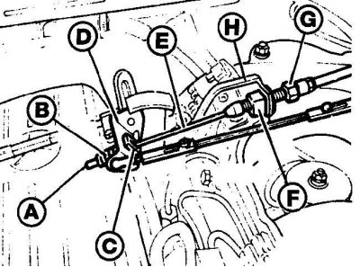


A – end of accelerator cable; B – spring; C – mounting block; D – guide lever; E – accelerator…

A – end of accelerator cable; B – spring; C – mounting block; D – guide lever; E – accelerator cable; F – plastic retainer; G – adjusting nut; H – bracket


Fastening the accelerator cable on 6-cylinder diesel engines
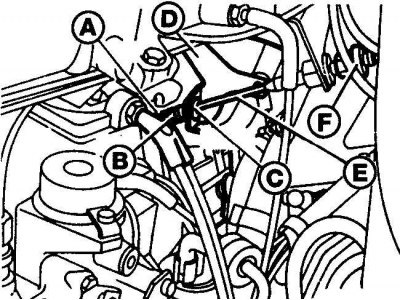


A – end of accelerator cable; B – spring; C – mounting block; D – guide lever; E – accelerator…

A – end of accelerator cable; B – spring; C – mounting block; D – guide lever; E – accelerator cable; F – adjusting nut


Location of the accelerator cable adjusting nut
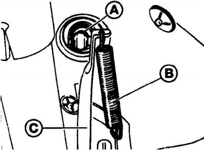


A – adjusting nut; B – spring; C – accelerator pedal

A – adjusting nut; B – spring; C – accelerator pedal


Roller axis (4- and 5-cylinder diesel engines)
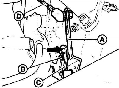


A – transmission lever; B – roller axis; C – thrust lever; D – thrust

A – transmission lever; B – roller axis; C – thrust lever; D – thrust


With the transmission lever in its original position, the roller axis should align with the groove in the lever (4- and 5-cylinder diesel engines).

Roller axis (6-cylinder engine)
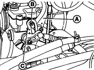


A – transmission lever; B – roller axis; C – thrust lever

A – transmission lever; B – roller axis; C – thrust lever


With the transmission lever in its initial position, the roller axis should be aligned with the end of the lever slot (six-cylinder engine).

The location of the connecting rod, the length of which can be adjusted
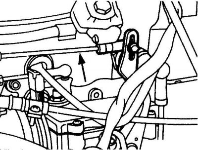


The location of the connecting rod, the length of which can be adjusted


High pressure fuel pump control lever
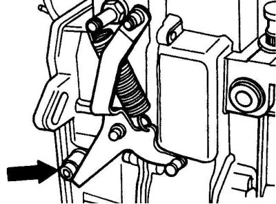


High pressure fuel pump control lever


When the accelerator pedal is fully depressed, the high-pressure fuel pump control lever should rest against the load limiter.


Adjustment (4- and 5-cylinder diesel engines)
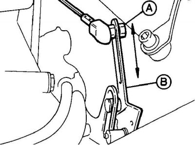


Adjustment (4- and 5-cylinder diesel engines)


To adjust, loosen the nut (A) and move it along the groove of the transmission lever (B) on 4- and 5-cylinder diesel engines.

Adjustment (6-cylinder diesel engines)
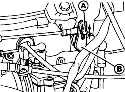


Adjustment (6-cylinder diesel engines)


To adjust, loosen the nut (A) and move it along the groove of the transmission lever (B) on 6-cylinder diesel engines.

1. Check that the accelerator cable is not twisted or kinked. Press the accelerator pedal all the way down. It should move smoothly and gently, without sticking.

2. With the accelerator pedal in the rest position, check that the plate at the end of the accelerator cable just touches the spring (see fig. Fastening the accelerator cable on 4- and 5-cylinder diesel engines, Fastening the accelerator cable on 6-cylinder diesel engines).


3. Otherwise, remove the driver's side lower trim panel and expose the grommet in the engine compartment bulkhead through which the accelerator cable passes (see Fig. Location of the accelerator cable adjusting nut). Turn the adjusting nut located on the engine compartment bulkhead until the plate at the end of the accelerator cable touches the spring.

4. With the transfer lever in the initial position, the roller axis should be aligned with the end of the stop lever. If necessary, adjust the length of the rod (see Fig. Roller axis (4- and 5-cylinder diesel engines), Roller axis (6-cylinder engine), Location of the connecting rod, the length of which can be adjusted).

5. Press the accelerator pedal all the way down. Check that the high-pressure fuel pump control lever touches the load limiter. In this position, check that the pivot point of the transmission lever is 1 mm from the end of the stop lever (see Fig. High Pressure Fuel Pump Control Lever).

6. Otherwise, loosen the tie rod end fastening nut and move the rod along the groove to a position to obtain the correct stroke, and tighten the fastening nut (see Fig. Adjustment (4- and 5-cylinder diesel engines), Adjustment (six-cylinder diesel engines)).

7. On vehicles with automatic transmission, adjust the pressure control cable.

8. Press the accelerator pedal fully and check that the high-pressure fuel pump control lever rests against the load limiter. Otherwise, adjust by turning the adjusting nut on the accelerator cable bracket (see Fig. Fastening the accelerator cable on 4- and 5-cylinder diesel engines and Fastening the accelerator cable on 6-cylinder diesel engines).
This article is available at: russian, bulgarian, belarusian, ukrainian, serbian, croatian, romanian, polish, slovak, hungarian
The article has been verified: Levin Kirill Glebovich
Share with friends:
◀ Previous
E-Class W124 / Diesel fuel system
Next ▶

Intake manifold — removal and installation
Air filter — removal and installation
General information about the diesel fuel system
Technical characteristics of the diesel fuel system
High pressure fuel pump — removal and installation
Fuel lift pump — removal and installation
Injection timing adjustment mechanism, fuel pump sprocket
High pressure fuel pump injection timing
Fuel injectors — removal and installation
More similar articles for repairing other models

☛ Accelerator pedal stop — adjustment Mercedes W168 (1997-2004)
☛ Throttle Cable — Removal, Installation and Adjustment Mercedes 190 (W201) (1982-1993)
☛ Removal, installation and adjustment of actuator cylinders and… Mercedes W463 (1999-2019)
☛ Seat adjustment Mercedes W163 (1997-2005)
☛ Seat adjustment Mercedes W140 (1991-1998)
☛ Idle speed adjustment Mercedes Sprinter (1995-2000, diesel)
Link in different formats to this article
Comments and feedback from visitors
No comments yet


How much will 43 + 11 ?


W210 (1996-2002) 
  • General information
  • Vehicle description
  • Working conditions and tools
  • Car care
  • Diesel engines
  • Engine repair
  • Lubrication system
  • Cooling system
  • Injection system
  • Supply system
  • Exhaust system
  • Gasoline engines
  • Engine repair
  • Lubrication system
  • Cooling system
  • Control system
  • Power and exhaust system
  • Transmission
  • Clutch
  • Mechanical gearbox
  • Automatic gearbox
  • Drive shafts
  • Chassis
  • Car suspension
  • Steering
  • Tires and wheels
  • Brake system
  • Body
  • Exterior (external elements)
  • Interior (internal elements)
  • Doors and windows
  • Heating and ventilation
  • Electrical equipment
  • Equipment and devices
  • Power devices
  • Lighting and signaling
  • Electrical circuits
W124 (1984-1995) 
  • General information
  • Governing bodies
  • Driving and operation
  • Weekly care
  • Maintenance (gasoline)
  • Maintenance (diesel)
  • Troubleshooting
  • Power unit
  • I4 petrol engine
  • V6 petrol engine (SOHC)
  • V6 petrol engine (DOHC)
  • Diesel engines
  • Engine overhaul
  • Cooling system
  • Heating and ventilation
  • Fuel system (carburetor)
  • Injection system «Bosch CIS-E»
  • Injection system «Bosch HFM»
  • Diesel fuel system
  • Supply system
  • Starting and charging system
  • Ignition system (I4)
  • Ignition system (V6)
  • Preheating
  • Transmission
  • Clutch
  • Mechanical gearbox
  • Automatic gearbox
  • Drive shafts
  • Chassis
  • Brake system
  • Car suspension
  • Steering
  • Body
  • Exterior (external elements)
  • Interior (internal elements)
  • Doors, locks and windows
  • Electrical equipment
  • Equipment and devices
  • Switches
  • Headlights and lighting
  • Electrical circuits
W123 (1976-1985) 
  • General information
  • Introduction to the guide
  • Power unit
  • Engine device
  • Repair M102 engines
  • Repair M110 and M123 engines
  • Cooling and lubrication (M102)
  • Cooling (M110 and M123)
  • Ignition system
  • Power system «Stromberg»
  • Power system «Solex 4A1»
  • Fuel injection «K-Jetronic»
  • Fuel injection «L-Jetronic»
  • Transmission
  • Clutch
  • Mechanical gearbox
  • Automatic gearbox
  • Cardan and rear axle
  • Chassis
  • Front suspension
  • Rear suspension
  • Steering
  • Brake system
  • Body
  • Exterior (external elements)
  • Interior (internal elements)
  • Doors, locks and windows
  • Electrical equipment
  • Equipment and devices
  • Power devices
  • Electrical circuits
 
MercedesMan.ru © 2017–2026 · Mobile version · Read about Mercedes · Sitemap: EN BG BY UA RS HR RO PL SK HU · Feedback · Site search · Bookmark A-Class (W168) · C-Class (W201) · C-Class (W202) · C-Class (W203) · E-Class (W123) · E-Class (W124) · E-Class (W210) · G-Class (W463) · M-Class (W163) · S-Class (W116, petrol) · S-Class (W126, petrol) · S-Class (W140) · S-Class (W220) · Sprinter · Vito 1 · Vito 2 · Vario 814D ·
 
We only use cookies without which some of the site's features may not be available.