
Removing
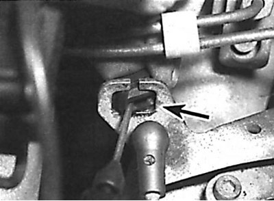
Removing the square fastener to release the accelerator cable
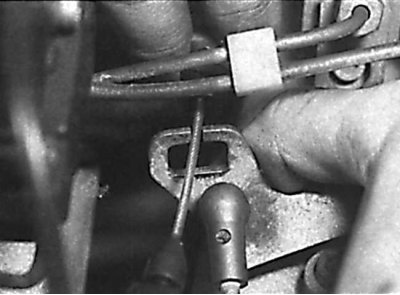
Removing the accelerator cable by passing it through the groove in the arm bracket
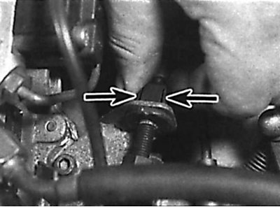
Location of accelerator cable sheath fixing brackets
Attaching the accelerator cable to the accelerator pedal
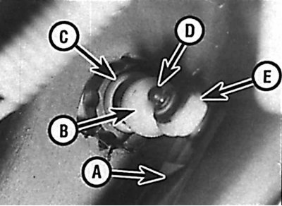
A - lever located at the top of the accelerator pedal; B – a nut of adjustment of a free wheeling of a pedal of an accelerator; C - sealing ring; D - pin for fastening the return spring; E - accelerator cable
1. Remove the ground wire from the battery.
2. In the engine compartment, remove the accelerator cable, after removing the square fastener (see fig. Removing the square fastener to release the accelerator cable, Removing the accelerator cable by passing it through the groove in the arm bracket). Remove the accelerator cable by passing it through the groove in the arm bracket.
3. Press the locking tabs and release the accelerator cable sheath from the bracket (see fig. Location of accelerator cable sheath fixing brackets).
4. Remove the trim panel located under the instrument panel on the driver's side. Remove the return spring and disconnect the accelerator cable from the accelerator pedal lever. Unscrew the adjusting nut, then remove the accelerator cable through the seal of the bulkhead of the engine compartment (see fig. Attaching the accelerator cable to the accelerator pedal).
Attention! Do not remove the accelerator cable o-ring from the interior bulkhead of the engine compartment.
5. On the outer partition of the engine compartment, remove the sealing ring and remove the accelerator cable into the engine compartment.
Installation
Elements of the accelerator cable and throttle linkage
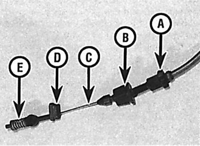
A - fully open throttle position limiter; B - plastic retainer; C - cable; D - square block for fastening the accelerator cable; E - spring
1. Installation is made in sequence, return to removal. Before connecting the accelerator cable to the throttle linkage, adjust the throttle linkage and throttle cable (see picture).
Adjustment
Attention! On vehicles with ASP speed control, adjusting the throttle linkage is a very difficult operation and must be done at a workshop.
Guide arm installation
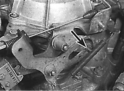
Set the guide lever in such a position that the roller is aligned with the edge of the idle speed limiter.
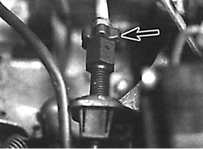
Location of the throttle valve open adjustment nut
Accelerator cable sheath end
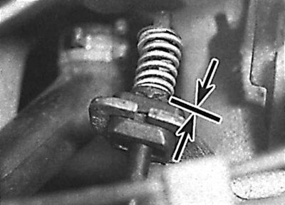
The end of the accelerator cable sheath must be in contact with the spring.
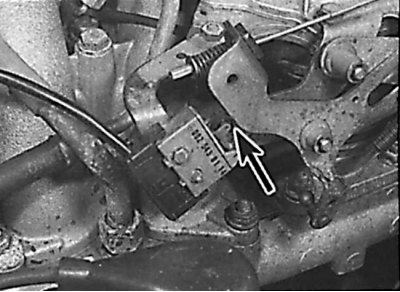
Location of the guide arm that activates the microswitch
1. Check that the cable and accelerator rod move smoothly and without jamming. Lubricate the accelerator link if necessary.
2. At the throttle body, remove the accelerator cable from the guide arm after removing the square fastener. Remove the accelerator cable through the groove on the guide arm bracket.
3. Remove the connecting arm from the spherical seat on the guide arm. The connecting lever is flat shaped and the adjusting lever connects the guide lever to the throttle lever.
Attention! On 2962cc3 DOHC engines, the link arm length can be adjusted without removing it from the pilot arm.
4. Set the guide arm in such a position that the roller is aligned with the edge of the idle speed limiter (see fig. Guide arm installation). In this position, fix the rod, loosen the mounting bolt and adjust the length of the connecting arm so that it is aligned with the spherical seat of the guide arm.
5. Install the accelerator cable to the guide arm. On automatic transmission models, disconnect the pressure control cable from the control arm.
6. On vehicles with a manual transmission, the assistant must depress the accelerator pedal to the stop, and on vehicles with an automatic transmission, depress the pedal to the position at which a downshift is forced into a downshift.
7. In this position, the throttle lever should align with the throttle stop. Otherwise, turn the adjusting nut in the bracket to reach this position (see fig. Location of the throttle valve open adjustment nut).
8. Release the accelerator pedal to its original position. In this case, the thrust roller must be aligned with the idle speed limiter on the guide lever. In this position, the end of the accelerator cable sheath should rest against the spring, and the guide lever should close the switch (see fig. Accelerator cable sheath end, Location of the guide arm that activates the microswitch). To adjust this position, turn the nut on the end of the cable on the side of the accelerator pedal (see fig. Attaching the accelerator cable to the accelerator pedal).
9. On vehicles with automatic transmission, connect the pressure control cable and adjust it.