
Stretching device
Removing
1. Being on the right side of the engine, unscrew the tensioner housing (do not unscrew the plug of the tensioner) from the cylinder head. Remove the O-ring (See fig. 8.1 a and 8.1 b).
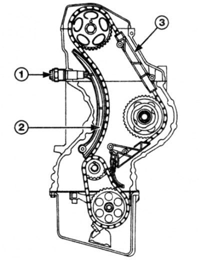
Pic. 8.1 a Tensioner and camshaft drive chain guides
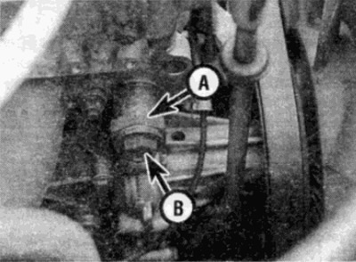
Pic. 8.16 Camshaft timing chain tensioner housing (A). Don't open the plug (IN)
Inspection
2. Do not attempt to disassemble the tensioner mechanism. If there is a suspicion of a breakdown or malfunction, the entire device should be replaced.
Installation
3. Before installing the tensioner, it must be filled with oil as follows.
- A) Place the tensioner, tappet side down, in a container of engine oil. The oil level must be above the level of the plug.
- b) Slowly press the device (a hydraulic press may be required to achieve the required force) 7-10 times. until the plunger reaches the stop.
- V) When the tensioner is correctly threaded, it should, when compressed, compress slowly, evenly, with little force.
4. Screw the tensioner into the cylinder head and tighten to the required torque.
Camshaft sprocket
Removing
5. Remove the accessory drive belt as described in chapter 1B.
6. Remove the camshaft cover as described in paragraph 4.
7. Remove the camshaft timing chain tensioner as described in this paragraph above.
8. If required, remove the self-adjusting suspension hydraulic pump from the front of the cylinder head as described in chapter 10. Remove the O-ring and gasket, then remove the bolt and remove the pump drive bush from the front of the crankshaft.
9. Make sure that the alignment marks on the crankshaft and camshaft are aligned correctly, as described in paragraph 3. Put alignment marks on the camshaft sprocket and chain.
10. After that, loosen the camshaft sprocket bolt. When doing this, the camshaft must be locked to prevent it from turning, this can be achieved by inserting a screwdriver into the hole of the sprocket - be careful not to damage the surrounding parts.
11. Turn away a bolt of fastening of an asterisk and remove a washer.
12. Remove the sprocket from the camshaft, remembering how it is installed.
Inspection
13. Check the wear of the sprocket teeth, each tooth forms a reverse letter "V". If they are worn, the side of each tooth under tension will be slightly concave when compared to the other side of the tooth (those. the teeth will look like a hook). If the teeth are worn, the sprocket should be replaced.
Installation
14. Make sure that the alignment marks on the crankshaft and camshafts are fully aligned, as described in paragraph 3. If a new sprocket is installed, transfer the alignment mark from the old sprocket to the new one.
15. Place the chain over the sprocket teeth, matching the marks made on the chain and on the sprocket before removing the chain.
16. Install the sprocket in its place on the camshaft, making sure that it is installed in the correct way, as noted before removal. Also check that the stud on the camshaft flange fits into the corresponding hole in the sprocket.
17. Install the mounting bolt and washer and tighten the bolt to the required torque while holding the sprocket as you did when removing.
18. If required, install the variable suspension hydraulic pump drive bushing to the front of the cylinder head and tighten the bolt to the correct torque as described in chapter 10. Install the gasket and O-ring (check and, if necessary, replace with new ones), then install the hydraulic pump as described in chapter 10.
19. Install the camshaft timing chain tensioner as described higher in this chapter.
20. Using a socket wrench on the pulley/damper-to-crankshaft hub bolt, turn the crankshaft one full turn and check that the timing marks on the crankshaft and camshafts are still in position corresponding to piston #1 reaching TDC as described. V paragraph 3.
Caution: Do not turn the engine over the camshaft sprocket.
21. Install the camshaft cover in accordance with paragraph 4.
22. Install the accessory drive belt as described in chapter 1B.
Crankshaft sprocket
Note: You will need an appropriate puller to remove the sprocket.
Removing
23. Remove the camshaft drive chain cover as described in paragraph 6.
24. Remove the oil pan as described in paragraph 11.
25. Remove the camshaft sprocket as described earlier in this paragraph. Use your hands to lower the camshaft drive chain down until it disengages from the crankshaft sprocket.
26. Separate the oil pump drive chain tensioner guide and spring from the lug on the cylinder block - remember the correct position of the spring to reproduce it during installation.
27. Turn away a bolt of fastening and remove an asterisk of a drive together with a chain from an axis of the oil pump. Remove the puck.
28. Apply alignment marks to the camshaft drive chain and crankshaft sprocket.
29. Using an appropriate puller, remove the sprocket from the front end of the crankshaft. You can remove the sprocket by using two large screwdrivers as levers on either side of the sprocket. Remember which way to set the asterisk to the correct position.
30. If it is loose, remove the segment key.
Inspection
31. Refer to paragraph 13.
Installation
32. If required, insert a key on the end of the crankshaft.
33. If installing a new sprocket, transfer the chain alignment mark from the old sprocket to it.
34. Engage the chain with the sprockets of the crankshaft and camshaft, making sure that the marks made before removing the chain are correctly aligned. After that, install the camshaft sprocket in its place, as described earlier in this paragraph.
35. Install the oil pump drive sprocket with chain (the convex side of the sprocket must face the pump). After making sure that the washer is in place, tighten the mounting bolt to the required torque.
36. Install the oil pump drive target tensioner guide bushing, spring, and then guide. Make sure the spring is installed correctly, just as it was before removal.
37. Install the oil pan as described in paragraph 11.
38. Install the camshaft drive chain cover as described in paragraph 6.
High pressure fuel pump sprocket
39. The description of this operation is part of chapter 4.
Tensioner guide
Removing
40. Remove the cylinder head as described in paragraph 10.
41. Remove the camshaft drive chain cover as described in paragraph 6.
42. Remove the camshaft drive chain tensioner as described earlier in this paragraph.
43. Pull the tensioner guide out of the clips.
Inspection
44. Check guide and replace if severe wear, damage or cracks.
Installation
45. Insert the tensioner guide into place, making sure that it is correctly clamped by the latches.
46. Install the camshaft timing chain tensioner as described earlier in this paragraph.
47. Install the camshaft drive chain cover as described in paragraph 6.
48. Install the cylinder head as described in paragraph 10.
Top guide
Caution: For this operation you will need a sliding hammer with an appropriate adapter, as well as sealant, which will be needed in order to lubricate the fixing pin of the guide.
Removing
49. Remove the camshaft sprocket as described above in this paragraph.
50. Screw a suitable bolt into one of the studs on which the guide is mounted (Studs are accessible from the front of the head block)
51. Hook the adapter onto the screwed bolt and use a sliding hammer to remove the stud (See fig. 8.51 a, b).
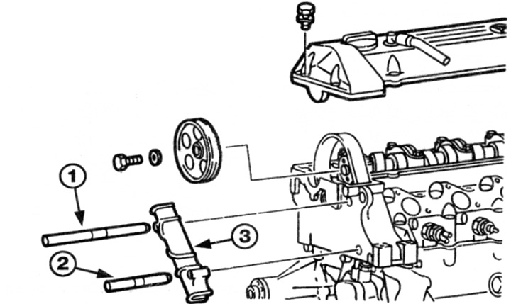
Pic. 8.51 a. Integral top camshaft chain guide
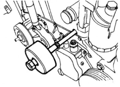
Pic. 8.51b. Using a sliding hammer, remove the camshaft timing chain guide retaining pin
52. Repeat the steps to remove the second pin. Take care to ensure that without the pin removed, the guide does not slide down the chain.
53. Remove the guide from the cylinder head.
Inspection
54. Refer to item 44.
Installation
55. Attach the guide to its installation site, insert the studs into the holes in the cylinder head and hammer them so that they hold the guide.
56. Apply sealant to the outer collar of both studs, where they are installed on the cylinder head, and hammer them all the way into the cylinder head.
57. Install the camshaft sprocket as described earlier in this paragraph.
Bottom guide
Removing
58. Remove the camshaft drive chain cover as described in paragraph 6.
59. Remove the camshaft drive chain tensioner as described earlier in this chapter.
60. Remove the guide from the mounting studs.
Inspection
61. Refer to item 44.
Installation
62. Install the guide on the mounting studs.
63. Install the camshaft timing chain tensioner as described earlier in this chapter.
64. Install the camshaft drive chain cover as described in paragraph 6.