
Removing
Attention: Before removing the camshaft, you can check the condition of the valves, as described in points 10 to 18. When installing, a new camshaft thrust half-ring may be required (see chapter 2D).
1. Remove the camshaft drive sprocket as described in paragraph 8.
2. The crankshaft bearing caps must be numbered from the drive chain to the engine. Check the number marks on the bearing caps and, if required, mark appropriately using a quick-drying felt-tip pen or punch.
3. Bolts of fastening of covers of bearings should be weakened in view of the following remarks.
Caution: To avoid damage to the camshaft, it is absolutely essential to follow the correct sequence in which you loosen the camshaft bearing cap bolts, 4-cylinder engine (see fig. 9.3a).
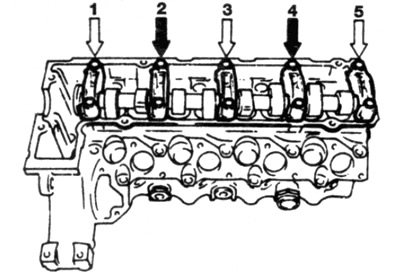
Pic. 9.3a Sequence of loosening the bolts of the bearing caps - 4-cylinder engine
Remove bearing caps 1, 3 and 5 (light arrows), then loosen, by turning one turn, the bolts of covers 2 and 4 (dark arrows)
- A) Gradually loosen and then remove the bolts from bearing caps 1, 3 and 5.
- b) Remove the upper halves of the bearings 1, 3 and 5 and lay them down, keeping their relative position. Pay attention to the pins on which the upper halves are put on: if the pins are stuck, they must be removed by gently tapping with a soft-tipped straightening hammer.
- V) Gradually loosen the bearing cap bolts 2 and 4, turning them only one turn each time, until the pressure on the camshaft is completely relieved. Be careful not to create an uneven load on the camshaft when loosening the bolts.
- G) Completely unscrew the remaining bolts and remove the upper halves of the bearings (2 and 4), also maintaining their relative position.
- d) Lift the camshaft off the cylinder head.
5 cylinder engine (see fig. 9.3b)
Pic. 9.3b Sequence of unscrewing the bolts of the bearing caps - 5-cylinder engine
Remove bearing caps 1, 2 and 3 (light arrows), then loosen, by turning one turn, the bolts of covers 3, 4 and 5 (dark arrows)
- A) Gradually loosen and then remove the bolts from bearing caps 1, 2 and 6.
- b) Remove bearing caps 1, 2 and 6 and lay them back in position. Pay attention to the pins on which the covers are put on: if the pins are stuck, they must be removed by gently tapping with a soft-tipped straightening hammer.
- V) Gradually loosen the bearing cap bolts 3, 4 and 5, turning them out only one turn each time, until the pressure on the camshaft is completely relieved. Be careful not to create an uneven load on the camshaft when loosening the bolts.
- G) Completely unscrew the remaining bolts and remove the bearing caps (3, 4 and 5), also maintaining their relative position.
- d) Lift the camshaft off the cylinder head.
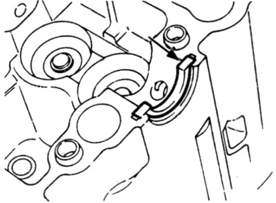
4. Remove the thrust half-ring limiting axial play, located on the rear bearing (see fig. 9.4)
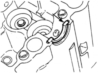
Pic. 9.4 Remove the thrust half-ring limiting axial play (shown by arrow)
5. Remove the hydraulic valve lifters from the holes in the cylinder head
Advice. Store each valve lifter in an oil-filled, labeled plastic jar.
Inspection
6. Check the bearings and cam surfaces for any signs of scuffing, scratching, and pitting caused by wear and, if found, replace the camshaft. Any damage of this nature will prevent the normal flow of oil in the cylinder head and careful inspection should ensure that no such obstruction occurs.
Valve tappets - a check that is carried out on the removed tappets
7. Inspect the valve lifters and gaskets. If you find signs of wear or destruction, replace them;
8. The normal operation of the valve lifters can be checked in the following order.
- A) Press about 10 seconds on the top of the piston of each of the pushers. using some blunt object for this, such as a wooden hammer handle.
- b) Notice how far the piston travels when compressed.
- V) Repeat this operation with each of the pushers in turn.
- G) If any of the pistons gives in to compression more easily than the rest, then replace the corresponding pusher.
9. Check the valve lifter holes in the cylinder head for wear and corrosion. If there is any serious damage, the cylinder head must be replaced.
Valve lifters - a check that is carried out without removing them
10. Start the engine, warm up to normal operating temperature.
11. Check the engine oil level, make sure it is not too high.
12. Remove the camshaft cover, in accordance with paragraph 4 — be careful: the engine is hot!
13. Crank the engine (clockwise), to bring cylinder #1 to TDC. Make sure that the alignment marks on the crankshaft and camshaft are correctly aligned as described in paragraph 3.
14. Make sure the valves are fully closed, i.e. camshaft lobe is up, then using a soft metal or hard wood rod, apply light pressure to the top of the #1 tappet at the front of the cylinder head (see fig. 9.14).
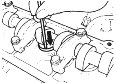
Pic. 9.14 Push the top of the tappet down to check the clearance between the tappet and camshaft lobe
15. While holding the valve lifter compressed, use a feeler gauge to measure the clearance between the valve lifter and the camshaft cam.
16. If the gap is greater than indicated in "Technical Data", the plunger must be replaced. Note that further disassembly of the pusher is possible, but it would be better if it is performed by a Mercedes-Benz dealer or an engineer with the appropriate qualifications.
17. Putting a socket wrench on the pulley / damper mounting bolt, turn the crankshaft and repeat the check of the remaining valve lifters. In each case, the corresponding valve must be completely closed, i.e. the camshaft lobe must point upwards.
Attention: When turning the crankshaft, do not use the camshaft sprocket bolt for this, and also do not turn the engine in the opposite direction (those. counterclock-wise).
18. When all valve lifters have been checked, install the camshaft cover in accordance with paragraph 4.
Installation
19. Lubricate the outer surfaces of the valve lifters with clean engine oil, then install them in their places in the cylinder block. Check that the pushers slide freely in their sockets.
20. Check up a condition of persistent half rings and, if necessary, replace them.
21. Lubricate the camshaft and bearing beds in the cylinder head with clean engine oil, then place the camshaft in its place in the cylinder head. The setting mark on the flange at the front of the camshaft must point upwards.
22. Put the bearing caps in place over the camshaft, making sure each cap fits exactly where it was removed from, and tighten the mounting bolts.
Caution: In order not to damage the camshaft, it is absolutely essential to follow the correct tightening sequence for the camshaft bearing cap bolts.
4 cylinder engine (see fig. 9.3a)
- A) Install the upper bearing caps 3 and 4, insert the bolts and gradually, turning one turn each time, tighten them to the required tightening torque. Be careful not to create uneven pressure on the camshaft when tightening the bolts.
- b) Install bearing caps 1, 3 and 5 and tighten bolts.
5 cylinder engine (see fig. 9.36)
- A) Install the upper halves of the bearing shells 3, 4 and 5, insert the bolts and gradually, turning one turn each time, tighten them to the required tightening torque. Be careful not to create uneven pressure on the camshaft when tightening the bolts.
- b) Install the upper halves of the bearing shells 1, 9 and 6 and tighten the bolts.
23. Install the camshaft drive sprocket as described in paragraph 8.