
Removing
Note: This operation may require a travel hoist. Appropriate sealant will be required during installation. It is recommended to replace the front crankshaft seal.
1. Disconnect the negative battery terminal.
2. Raise the engine hood as far as it will go as described in chapter 11.
3. Remove the engine crankcase protection.
4. Remove the heat sink and driven fan as described in chapter 3.
5. Remove pulley/damper as described in paragraph 5.
6. Remove the accessory drive belt tensioner in the following order.
- A) Pull out the plastic plug, unscrew the bolt and remove the auxiliary drive belt idler pulley.
- b) Loosen the bolt and remove the fan drive pulley.
- V) Loosen the bolt and remove the tensioner damper post, noting the location of the shims and/or brackets.
- G) Using pliers, separate the tensioner spring, noting its position so that the spring can be properly installed during reassembly.
- d) If required, pull out the plastic cover, unscrew and remove the tensioner mounting bolt and remove the spacer.
- e) Remove the tensioner, remove the gasket.
7. Remove the brake booster pump as described in chapter 9.
8. Remove the power steering/adjustable suspension pump as described in chapter 10.
9. If necessary, remove the variable suspension hydraulic pump from the front of the cylinder head as described in chapter 10.
10. Remove the alternator as described in chapter 5.
11. Drain the engine oil as described in chapter 1B.
12. Remove the camshaft cover as described in paragraph 4.
13. On models with air conditioning, place a sheet of cardboard or some other shield in front of the condenser to protect it from damage during subsequent operations.
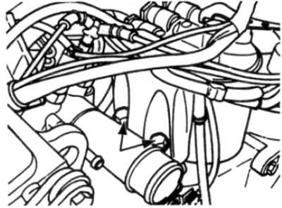
14. Remove the two bolts from the front of the fuel filter/thermostat assembly (see fig. 6.14).
15. Turn away from a head of cylinders a tube of a dipstick of level of oil in the engine.
16. Turn away bolts and remove the arm supporting the generator, remembering an arrangement of bolts.
17. If available, mark the position of the crankshaft rotation sensor bracket on the camshaft drive chain cover and remove the bracket bolts.
18. If present, unscrew the fixing bolts and remove the engine vibration limiter, in accordance with paragraph 16.
19. If necessary, unscrew the two bolts and disconnect the lower end of the engine mount shock absorber on the left side from the cross beam.
20. Route the travel hoist slings under the front engine mount.
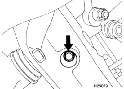
21. Being under the car, turn away two lower bolts of fastening of the engine (one on each side) (see fig. 6.21)
22. Using a lift, raise the engine so that you can access the bolts securing the oil pan to the camshaft drive chain cover.
23. Unscrew and remove the bolts securing the oil pan to the cover of the camshaft drive chain, loosen the remaining bolts of the pan.
24. Lower the engine so that it rests on the supports.
25. While holding the nuts, remove the three bolts securing the high pressure fuel pump to the camshaft drive chain cover (see fig. 6.25).
26. Working through the hole on top of the cylinder head, unscrew the two bolts securing the cylinder head to the camshaft drive chain cover (see fig. 6.26)
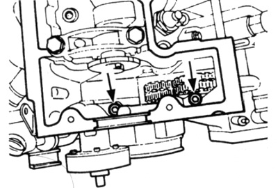
Pic. 6.26 Remove two bolts (shown by arrows) attaching the cylinder head to the camshaft timing chain cover
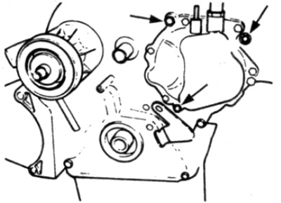
27. Gradually unscrew the remaining bolts securing the chain cover, remembering the location of each of them. (see fig. 6.27)
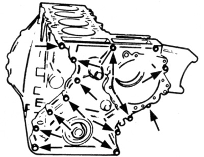
Pic. 6.27 Loosen the remaining cover bolts (shown by arrows)
28. Gently pull the cover forward from the cylinder block. If the cover is tight, lightly tap the edges with a hammer with a protected striker - do not use a lever inserted between the cover and the cylinder block for this.
Caution: Be careful not to damage the cylinder head and oil pan gaskets when the timing chain cover is removed.
Installation
29. Begin installation by thoroughly cleaning the adjacent surfaces of the camshaft timing chain cover, cylinder block and cylinder head. Remove all traces of old sealant.
30. Carefully check the condition of the cylinder head gasket. If the gasket is found to be damaged, the cylinder head must be removed to replace the gasket as described in paragraph 10.
31. Similarly, carefully check the condition of the oil pan gasket. If the gasket is damaged during disassembly, the oil pan must be removed to replace the gasket, as described in paragraph 11.
32. It is recommended to replace the crankshaft seal in the cover, adhering to the following order.
- A) Pry off the old cuff using a screwdriver.
- b) Clean the oil seal seat in the crankshaft drive chain housing.
- V) Hammer in a new cuff (dry) in its place, using a suitable pipe or socket wrench, so that it rests against the ledge.
33. Wrap a piece of polyethylene or adhesive tape around the front end of the crankshaft flange to prevent damage to the cuff when installing the cover.
34. Apply sealant to the surface of the camshaft timing chain cover adjacent to the cylinder block.
35. Lubricate the edge of the cuff with engine oil, then install it in place. Be careful not to damage the edge of the cuff, as well as the cylinder head and pan gaskets, when installing the cover.
36. Insert the bolts securing the chain cover to the cylinder block, then gradually tighten them with the required torque.
37. Insert the bolts of the cylinder head to the chain cover and tighten them to the required torque.
38. If you used it, remove the protective plastic from the front end of the crankshaft.
39. Install and tighten the high pressure fuel pump bolts and nuts.
40. Hoist with a winch, raise the engine to be able to install the bolts securing the pallet to the chain cover.
41. Install the bolts securing the pallet to the chain cover and gradually tighten them to the required torque.
42. Lower the engine onto stands. then install and tighten the lower engine mounting bolts.
43. If provided, install the bolts securing the engine damper to the frame cross member.
44. If provided, install and lock the engine travel limiter as described in paragraph 16.
45. If necessary, install the crankshaft position sensor mounting bracket. making sure the bracket is aligned with the marks. made before removal.
46. Install the alternator bracket, making sure the bolts are in place.
47. Install the oil filler bolt to the cylinder head.
48. If required, install the fuel filter/thermostat assembly mounting bolts.
49. If it is, remove the protective shield from the air conditioner condenser.
50. Install the camshaft cover, in accordance with paragraph 4.
51. Install the generator, in accordance with chapter 5.
52. If equipped, install the variable suspension hydraulic pump to the cylinder head in accordance with chapter 10.
53. Install the hydraulic pump for power steering/etching/adjustable suspension as described in chapter 10.
54. Install the brake booster pump as described in chapter 9.
55. Install the accessory drive belt tensioner in the reverse order to that described in paragraph 5.
56. Install the pulley / damper and crankshaft hub in accordance with paragraph 5.
57. Install the fan drive assembly and heatsink as described in chapter 3.
58. Install the lower engine protection.
59. Fill the engine with the appropriate amount of engine oil of the required quality, as described in chapter 1B.
60. Connect the negative battery terminal and lower the hood.