
Removing
Warning: This operation requires a traveling hoist and a sliding hammer. A new cylinder head gasket and coolant elbow O-ring will be required during installation. May also require new cylinder head bolts (see text).
1. Before proceeding with the removal of the cylinder head, make sure that the engine is cold; note that the cylinder head will be removed along with the exhaust manifold.
2. Disconnect the negative battery terminal.
3. Raise the engine hood as far as it will go as described in chapter 11.
4. Drain engine oil and coolant as described in chapter 1B.
5. Remove the camshaft as described in paragraph 9.
6. Remove the nozzles as described in chapter 4.
7. Remove the heatsink as described in chapter 3.
8. Remove the accessory drive belt tensioner in the following order (see fig. 10.8).
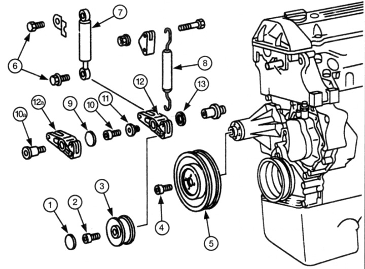
Pic. 10.8 Components of the accessory drive belt tensioner
1 plastic cover
2 Bolt
3 Intermediate pulley
4 Bolt
5 Fan pulley
6 Bolts
7 Tensioner damper
B Tension spring
9 Plastic cover
10 Bolt
10a Other type of bolt
11 Sleeve
12 Tensioner
12a Other type of tensioner
13 Sleeve
- A) Remove the plastic cover, unscrew the fastening bolt and remove the auxiliary drive belt tension pulley.
- b) Loosen the mounting bolt and remove the radiator fan pulley.
- V) Loosen the bolts and remove the tensioner damper. Remove all spacers and/or brackets, noting their location.
- V) Using pliers, unhook the tension spring, remembering its correct position in order to restore it during assembly.
- G) If required, remove the cover and unscrew the bolt securing the tensioner. pull out the bushing on which the tensioner is attached.
- d) Remove tensioner and remove bushing.
9. On non-turbo models, remove the air cleaner housing, inlet pipe and filter element as described in Chapter 4.
10. On models with a turbocharger carry out the following operations.
- A) Remove the turbocharger inlet pipe.
- b) Unscrew the turbocharger mounting bracket.
- V) Unscrew the union nut and disconnect the turbocharger oil return line from the cylinder block.
11. Lay a rag near the fuel line connector to the fuel filter, then unscrew the player nuts and disconnect the fuel line, note the location of the parts for proper assembly (see fig. 10.11). Plug the open ends of fittings and pipes to prevent dirt from entering the fuel line and fuel from spilling.
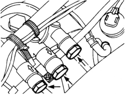
Pic. 10.11. Disconnect fuel lines (shown by arrows)
12. Turn away bolts from a head of cylinders and remove the filter.
13. Turn away bolts and remove a tube of a dipstick of level of oil from a head of cylinders.
14. On models with exhaust gas recirculation, disconnect the pipe from the exhaust gas recirculation valve (see fig. 10.14).
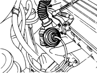
Pic. 10.14 Disconnect the hose (shown by arrow) from the exhaust gas recirculation valve
15. Working from below the vehicle, first remove the bolts securing the exhaust system bracket to the gearbox, and then the bolts that secure the bracket to the exhaust system.
16. Disconnect the front section of the exhaust system from the manifold, in accordance with chapter 4.
17. Using a suitable tool with a bent end or a piece of wire, release the latch of the clamp on the bent pipe that supplies coolant to the oil cooler (see fig. 10.17)
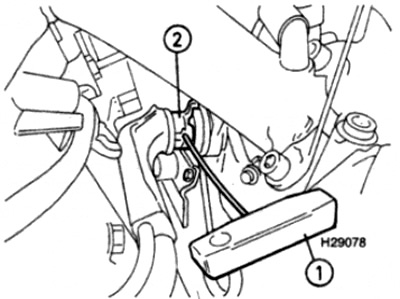
Pic. 10.17 Use a tool with a bent end (1), to pull out the retaining ring (2) on the cooling system pipe
18. Unscrew the elbow from the oil filter assembly, then pull it out of the connector.
19. Turn away nuts and disconnect a socket from a glow plug.
20. Remove the intake manifold as described in chapter 4.
21. Remove the upper camshaft drive chain guide as described in paragraph 8.
22. Remove the two bolts securing the cylinder head to the camshaft drive chain cover, which can be accessed from under the chain cover.
23. Make a final check to make sure that all pipes and wires are disconnected and will not interfere with removal of the cylinder head.
24. Gradually loosen the cylinder head bolts in the reverse order shown in fig. 10.43a and 10.436.
25. Remove the cylinder head bolts, remembering their location, since the bolts are of different lengths.
26. Hook the hoist slings onto the rigging brackets on the front left of the cylinder head and rear right of the exhaust manifold. The lift capacity must match the weight of the cylinder head.
27. Separate a head of cylinders from the block of cylinders and pins, swinging it. Do not insert a tool between the mating surfaces to do this, as this may damage the cylinder head gasket.
28. Carefully lift the cylinder head together with the exhaust manifold and remove it from the engine compartment.
29. Remove the cylinder head gasket.
Inspection
30. Refer to chapter 2D, where the disassembly of the cylinder head is described in detail. If you want to remove the exhaust manifold, please contact chapter 4.
31. Before installing the head, the mating surfaces of the cylinder head and cylinder block must be thoroughly cleaned. Use a scraper to remove all gasket marks and deposits; also clean the tops of the pistons. Be especially careful with the cylinder head, as it is easy to damage its metal. Also check that small particles do not get into the open holes of the oil and water channels. Use masking tape and paper to cover all of these holes and bolt holes in the cylinder block. To prevent carbon clogging, put a little grease into the gap between the piston and cylinder liner. After cleaning each piston, while turning the crankshaft so that the piston moves down inside the cylinder, wipe off the grease and deposits with a wiping cloth,
32. Check the block and head for dents, deep scratches and other damage. Minor damage can be carefully removed from the surface of the cylinder block with a file. More serious damage should be repaired by grinding, but this work should be done by a specialist.
33. If there is suspicion of warping of the cylinder head, attach a metal ruler and check the curvature of the surface, in accordance with chapter 2D.
34. Clean the bolt holes using compressed air or a thin cloth wrapped around the screwdriver. Make sure that all traces of water or oil are removed, otherwise cracks may form in the block due to hydraulic pressure when tightening the bolts.
35. Check up, whether the carving on bolts and in apertures in the block of cylinders is damaged. If necessary, re-thread the block with a suitable tap.
36. The manufacturer recommends measuring the length of the bolts to determine which bolts need to be replaced; on the other hand, some car owners prefer to replace all bolts with new ones, regardless of their condition
37. Measure the length of each bolt, from the base of the head to the end of the shaft (see fig. 10.37). If the bolt length exceeds the maximum value specified in the Technical Data section", the bolt must be replaced.
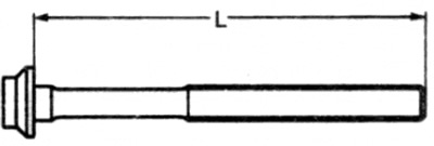
Pic. 10.37 Measure the length (L) cylinder head bolts
The value of the maximum length is given in the section "Technical data"
Installation
38. If required, install the exhaust manifold in accordance with chapter 4.
39. Make sure. when cylinder #1 is at TDC, the timing marks on the crankshaft and camshaft are correctly aligned as described in paragraph 3.
40. Put a lining on the block of cylinders, having established it on pins.
41. Using the lifting mechanism to support the cylinder head, lower it onto the block.
42. Lubricate the threads and surfaces of the cylinder head bolts in contact with the cylinder head (see paragraphs 36 and 37), then insert the bolts and hand-tighten them into the cylinder block. Make sure all bolts are in place. noted during disassembly.
43. Tighten the bolts in the order shown (see fig. 10.43, a, b). Tighten the bolts in several steps as specified in "Technical Data" tightening torques for each stage: i.e. first tighten all bolts to the torque setting specified for step 1, then tighten all bolts to the torque step 2, and so on.
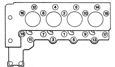
Pic. 10.43 a. Cylinder head bolt tightening order - 4-cylinder diesel engine
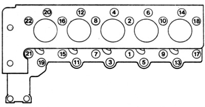
Pic. 10.43 b. Cylinder head bolt tightening order - 5-cylinder diesel engine
44. Install and tighten the cylinder head bolts to the camshaft drive chain cover.
45. Install the upper camshaft drive chain guide as described in paragraph 8.
46. Install the intake manifold as described in chapter 4.
47. Connect the connector to the glow plug and tighten the fastening nuts.
48. Install the bent coolant inlet pipe to the oil cooler using a new o-ring. Lubricate the ring with coolant before installation. Install retaining ring.
49. Attach the front section of the exhaust system to the exhaust manifold, in accordance with chapter 4.
50. Establish a bracket of fastening of an exhaust pipe to a transmission and tighten bolts of fastening. Make sure the exhaust system is secured without stress.
51. Perform further installation in order. reverse order for removal, taking into account the following points.
- A) Make sure the fuel lines are properly connected to the fuel filter as noted before removing them.
- b) Install the accessory drive belt tensioner in the reverse order of step 8.
- V) Install the heatsink as described in chapter 3.
- G) Install the nozzles as described in chapter 4.
- d) Install the camshaft as described in paragraph 9.
- e) Fill the cooling system and fill the engine with oil as described in chapter 1B.