



Contents: Cleaning ↡ Checking the status ↡
1. A thorough cleaning of the head and valve train components followed by a detailed inspection will determine what work needs to be done to restore the valve train.
Note: If the engine has been severely overheated, check to see if the cylinder head is warped.
Cleaning
2. Remove all traces of the old gasket from the cylinder head.
3. Scrape off carbon deposits from the combustion chamber and bores. Afterwards, thoroughly wash the cylinder head with kerosene or other suitable solvent.
4. Scrape off thick carbon deposits from the valve heads with a scraper, and finish cleaning the valve heads and stems of carbon deposits with a wire brush attached to an electric drill.
Checking the status
Note: Perform all of the following checks before deciding whether to contact a service station. Make a list of items that require attention.
Cylinder head
5. Carefully inspect the head for cracks, visible coolant leaks, or other damage. If cracks are found, the head must be replaced.
6. Using a ruler and feeler gauge, check for warping of the surface adjacent to the cylinder block (see fig. 9.6). If warping is detected, you can try to eliminate it by mechanical treatment. It is important not to go beyond the minimum head height. Note also that on diesel engines it is necessary to control the combustion chamber protrusion if the cylinder head surface is ground - see paragraphs 11-13.
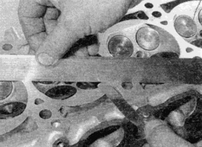
Fig. 9.6. Checking the warpage of the cylinder head surface using a metal ruler and feeler gauges
7. Check the valve seats in each combustion chamber. If they have significant pitting, cracks or burn-through, they must be replaced or reground by a specialist. If the seats and valves have only slight pitting, they can be ground with a special paste as described below. If the valve seats are reground, check that the valve recess, measured between the cylinder head sealing plane and the center of the valve disc, is within the required limits.
8. Check the valve guides for wear. Lower the valve into the appropriate hole and rock it from side to side. A slight play is acceptable. If there is significant play, check the valve stem diameter (see below) and replace it if worn. If the valve is not worn, the wear may be in the guide bushing. The guide bushing should be countersunk or replaced and a repair valve installed. It is best to replace the guide bushing at a service station that has all the necessary tools
9. If the valve seats need to be re-sharpened, this can only be done after replacing the guide bushings.
10. Check the camshaft bearing surfaces in the cylinder head and bearing caps for wear or damage. If the bearings are significantly worn, it may be necessary to ream the bore in the cylinder head/cap to install a camshaft with oversize journals. Consult your Mercedes-Benz dealer or engine repair specialist.
Combustion chambers - diesel engines
11. When checking the cylinder head, you should check the combustion chamber protrusion - this is especially important if the head has been ground. If the protrusion is too large, the pistons may hit the chamber when the engine is running, which will lead to serious damage.
12. Measure the protrusion of the combustion chamber from the sealing plane of the cylinder head (see fig. 9.12). If the protrusion exceeds the maximum allowable value, the protrusion can be adjusted by removing the combustion chamber and installing sealing linings of varying thickness to achieve the desired protrusion. If the head has been ground, inserts of increased thickness should be installed to match the thickness of metal removed from the head.
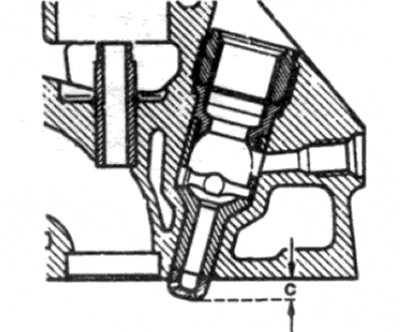
Fig. 9.12. Measuring combustion chamber protrusion (c) - diesel engines
13. Removal and installation of combustion chambers and installation of corresponding inserts should be entrusted to a Mercedes-Benz dealer or an engine repair specialist.
Valves
Warning: To improve heat transfer, the exhaust valves on 4-cylinder gasoline engines and diesel engines are sodium filled. Sodium filled valves may be installed on other engines. Sodium is a highly reactive metal that will ignite and explode when in contact with water [including water vapor in the air]. These valves should not be disposed of in the normal manner. Consult your dealer for advice.
14. Inspect each valve head for pitting, cracking, burnout, and general wear. Check the valve stems for scoring and wear. Rotate the valve to make sure it is not bent. Look for dents or excessive wear on the ends of the valve stems. Replace any valves that show such damage.
15. If the valve appears satisfactory at this stage of the inspection, measure the valve stem diameter at several places along the length using a micrometer (see fig. 9.15). Any difference in readings means that the rod is worn. If the wear is beyond acceptable limits, the valve must be replaced.
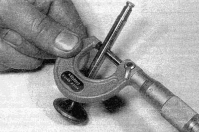
Fig. 9.15. Measuring the valve stem diameter
16. If the valves are in good condition, check their fit to the seat to ensure good gas sealing. If the seat has only slight pitting or has been reground, only fine paste should be used for finishing. Coarse paste should not be used for lapping unless the seat has deep pitting or burn-through. If this is the case, show the head and valves to a specialist who will decide whether the seat can be reground or whether the valve or seat insert must be replaced.
17. The valve grinding is performed as follows: Place the head upside down on a stand, placing a wooden block on each side.
18. Apply a small amount of lapping paste to the seat working surface and press the head of the valve lapping tool from above onto the valve disc (see fig. 9.18). Using reciprocating and rotating movements, grind the valve to the seat, occasionally lifting the valve to replace the paste. To facilitate this operation, it is recommended to insert a weak spring under the valve plate.
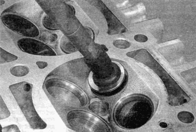
Fig. 9.18. Lapping valves using a device
19. When using coarse grinding paste, lap until all traces of pitting have disappeared and the lapped surfaces of the valve seat and head have a dull matte appearance. Then remove the remaining paste and proceed to work with fine paste. Continue lapping until a light, continuous annular band appears on both surfaces. Do not lap the valves more than necessary, otherwise the seat will drop below the head level prematurely.
20. After grinding all the valves, before assembling the head, thoroughly wash off all traces of the grinding paste with kerosene or another solvent.
Valve Mechanism Parts
21. Inspect the valve springs for damage and discoloration, and measure their free length by comparing the existing springs with the new one.
22. Place each spring on a flat surface and check it for shape retention. If any of the springs are damaged, out of shape, or have lost their elasticity, the entire set of springs should be replaced. It is considered normal to replace all springs during a major engine overhaul.
23. Replace all valve stem seals, regardless of their condition.
Tappet Gear / Valve Tappets
24. Check the contact surfaces. If significant wear or damage is found, the parts should be replaced. Refer to parts A, B and IN of this Chapter.