
Removing
Note: This operation requires an appropriate hoist and winch.
1. Follow the steps described in paragraph 4, p.p. 1-8, inclusive, given that it is not necessary to remove the air cleaner.
2. On non-turbo models, remove the intake air duct, then unfasten the fasteners and remove the air cleaner cover and filter (see fig. 6.2).
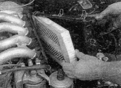
Pic. 6.2. Remove the air cleaner cover and filter
3. On turbo models, remove the compressor air inlet.
4. Working in the engine compartment, disconnect all required hoses and tubes so that they do not interfere with engine removal. Note the location and routing of all hoses and tubes so as not to confuse during installation. Where provided, remove all hoses and vacuum tubes from holders or brackets.
5. Similarly, acting in the engine compartment, disconnect the wires from the relevant parts and connectors. Remember the location and routing of all connections so as not to confuse during installation. Release all wires and wiring harnesses from holders and brackets on the engine.
6. On models with air conditioning, remove the accessory drive belt. as described in Chapter 1. Loosen the air conditioning compressor bolts as described in Chapter 3 and support it in the engine compartment, separating it from the engine, but without disconnecting the cooling pipes,
7. Turn away nuts of unions and disconnect the bringing and drain lines from the fuel filter and/or the pump of system of injection of fuel. Where required, hold fittings from turning.
8. Disconnect the throttle cable from the throttle control lever (if necessary, contact Chapter 4), then release the cable from all brackets on the engine and lay it aside.
9. Unscrew the reservoir cap of the power steering system and drain as much fluid as required. Use a large syringe. Close the tank with a lid when it is empty.
10. Where required, loosen the unions and disconnect the fuel hoses from the suspension/power steering hydraulic pump. Release the pipes from the holders and brackets on the engine.
11. Where provided, remove the wheel arch locker from the left side of the wheel arch, then unscrew the fittings and disconnect the oil pipes from the oil heat exchanger located under the wheel arch (talk to Chapter 2D for further information).
12. Where it is installed, unscrew the engine speed sensor from the flywheel side and release the wire from the holders. Leave the sensor with wiring harness in the engine compartment, taking care not to damage it.
13. On models with automatic transmission, unscrew the heat exchanger tubes from the engine sump and remove the assembly.
14. Disconnect the brake booster vacuum hose from the vacuum pump (see chapter 9).
15. Follow the steps described in paragraph 4, p.p. 23-28, inclusive.
Installation
16. Refer to paragraph 4, and 29.