



Cleaning
1. Remove all external parts, electrical switches and sensors from the unit. For a complete cleaning, it would be good to remove all technological plugs. To do this, drill a small hole in the plug and return the self-tapping screw to it. Pull out the plug, grasping the screw head with a vice or pliers.
2. Remove all traces of gasket from the cylinder block, taking care not to damage the surfaces.
3. Remove the longitudinal lubrication channel plugs (where they are installed). Please note that the plugs are very tight and will need to be drilled out. New plugs must be installed during assembly.
4. If the drinking parts are very dirty, they need to be cleaned with steam.
5. After the castings have been steam cleaned, clean all oil passages again. Rinse all internal cavities with warm water until the water runs clear. If possible, use compressed air to speed up the drying process and blow out all oil lines.
Warning: When using compressed air, protect your eyes!
6. If the cast parts are not very dirty, you can, as an option, wash them in hot soapy water (the water should be as hot as you can bear) with a stiff brush. Do not spare time for this work. Regardless of the cleaning method, be sure to clean all holes and cavities for the passage of oil and thoroughly dry all parts. To prevent rusting of the cylinder walls, cover them with a thin layer of clean motor oil.
7. Where installed, it is recommended to remove the piston oil spray nozzles from the cylinder block and clean them. To remove the nozzle, unscrew the mounting bolt, remove the sealing ring (where it is installed) and remove the nozzle from the block (see fig. 13.7). Replace any nozzles that are damaged. Check if the oil passages and nozzles are blocked.
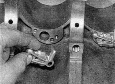
Fig. 13.7. Removing the piston oil spray nozzle from the cylinder block
8. In order to accurately maintain the required tightening torque during assembly, all threaded holes in the cylinder block must be completely clean. Carefully tap all holes with a tap of the required size (the size can be determined by the threads of the bolts removed from these holes), to remove dirt, rust, sealant residues from them, and also to restore the threads (see fig. 13.8). If possible, blow out the holes with compressed air after processing.
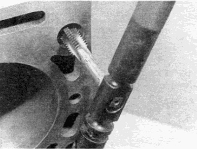
Fig. 13.8. Cleaning the threaded holes of the cylinder block using a suitable tap
Tip: An alternative method is to spray an aerosol dispersant into each hole using an extension nozzle.
Caution: Protect your eyes if you clean holes this way!
9. Make sure all threaded holes in the cylinder block are dry and clean.
10. After applying sealant to the mating surfaces of the new plugs, install them on the cylinder block. Make sure they are installed perpendicularly and correctly, otherwise leaks may occur.
11. Apply a coat of suitable sealant to the new longitudinal oil channel plugs and insert them into the block holes. Tighten them securely.
12. If you are not going to assemble the engine immediately, cover it with a large piece of polyethylene to protect it from dirt and dust; protect mating surfaces from corrosion as indicated above.
Inspection
Note: Certain diesel engines are equipped with dry cylinder liners. Where dry cylinder liners are installed, the liners can be replaced to compensate for cylinder wear rather than reboring. New dry liners can be installed on all engines by reboring the cylinder block accordingly. Liner replacement should be performed by a service station.
13. Check cast parts for corrosion and cracks. Check if the threads in the threaded holes are stripped. If there have been cases of internal coolant leaks during operation, it is better to contact an engine repair specialist to thoroughly check the block for cracks using special equipment. If such defects are found, send the block for repair, if possible, or replace the block.
14. Inspect each cylinder for nicks and scratches. Check for a wear step at the top of the cylinders, which indicates that the cylinder has increased wear.
15. If you have a suitable tool, measure the diameters of each cylinder at the top (just below the protruding belt), in the middle and at the bottom of the cylinder in a direction parallel to the crankshaft axis.
16. Then measure the diameters at the same points in the direction perpendicular to the shaft axis. Compare the results with the technical data. If there is no technical data, if you have any doubts about the condition of the cylinders, consult a Mercedes-Benz dealer or an engine specialist.
17. If the cylinder dimensions exceed the tolerances or the cylinder walls are scratched or have significant wear, the cylinders must be bored and new repair pistons installed. Repair pistons can be purchased at the Mercedes-Benz service station where cylinder boring is recommended. Recall that the piston and cylinder dimensions are stamped on the piston crown and on the cylinder block surface mating with the cylinder head.
18. Check for damage to the top surface of the cylinder block. Use a metal ruler and feeler gauges to ensure that the surface under the cylinder head gasket is not warped. If the surface is warped, it can be ground, checking that the block height is not lower than required by the specifications. Note also that when processing the surface of the cylinder head on diesel engines, it is necessary to check the piston protrusion - see item 19.
Piston protrusion - diesel engines
19. When checking the cylinder block, the piston protrusion should be checked - this is especially important if the cylinder head has been machined. If the piston protrusion is too large, the pistons may hit the combustion chamber during engine operation, causing engine failure.
20. Measure the piston protrusion from the cylinder head sealing surface (it is advisable to use an indicator micrometer). If the piston protrusion is higher than required by specifications, consult your Mercedes-Benz dealer or engine repair specialist - the cylinder block may need to be replaced.