
- A) On 4-cylinder petrol engines, remove the sump, camshaft timing chain and flywheel/faceplate as described in Part A of this Chapter. If desired, you can also remove the crankshaft sprocket.
- b) On 6-cylinder gasoline engines, remove the oil pump sump, lower drive chain case, drive chain, and flywheel/drive plate as described in Part B of this Chapter. If desired, also remove the crankshaft sprocket.
- V) On diesel engines, remove the sump, oil pump, oil deflector plate (where provided), chain cover, camshaft timing chain and flywheel/drive plate as described in parts of this chapter. If desired, also remove the crankshaft sprocket.
2. Turn out from a head of cylinders bolts of the case of a back cuff of a cranked shaft. Remove gasket (see fig. 12.2).
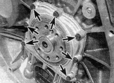
Pic. 12.2. Bolts of fastening of the case of a back collar of a cranked shaft - 4-cylinder petrol engine
3. Remove pistons and connecting rods as described in paragraph 11. If you do not plan to work on the pistons or connecting rods, it is not necessary to remove the cylinder head and push the pistons and connecting rods out. It is enough just to push the pistons deep into the cylinders to bring them out of connection with the crankshaft journals.
Warning: If the pistons are pushed up with the cylinder head not removed, be careful. so as not to hit the piston in the open valve.
4. Check the end play of the crankshaft as described in paragraph 15. After that, do the following.
5. On 4-cylinder engines, the crankshaft bearing caps must be numbered 1 through 5 from the drive chain end. Similarly, on 5-cylinder engines the covers must be numbered 1 to 6 and on 6-cylinder engines 1 to 7 (see fig. 12.5). If there are no marks, make them with a core.
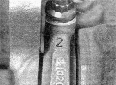
Pic. 12.5. Main bearing cap identification mark
6. Loosen and remove the main bearing cap bolts and remove each cap (see fig. 12.6). Remove the lower bushing and secure it with adhesive tape to the appropriate bearing cap. Where installed, note the location and orientation of the oil pickup tube bracket attached with the cap bolts.
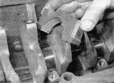
Pic. 12.6. Removing the main bearing cap
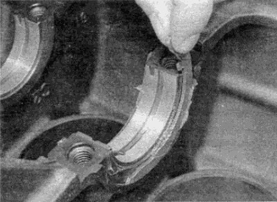
7. Remove the thrust washers from each side of the respective cover, noting the location (see fig. 12.7).
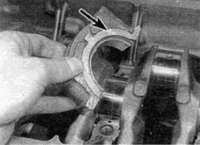
Pic. 12.7. Remove thrust washers (shown by arrows) from the bearing cap...
- A) 4-cylinder engines - middle cover (№3) main bearing.
- b) 5-cylinder engines - No. 4 main bearing cap.
- V) 6-cylinder engines - No. 5 main bearing cap.
8. Pull out the crankshaft. Be careful as it is heavy.
9. Remove the upper main bearing shells and place them together with their respective caps. Also remove two thrust half rings from the cylinder block, remembering their orientation (see fig. 12.9).
Pic. 12.9....and from the cylinder block