
Selection of new inserts
Four cylinder petrol engines
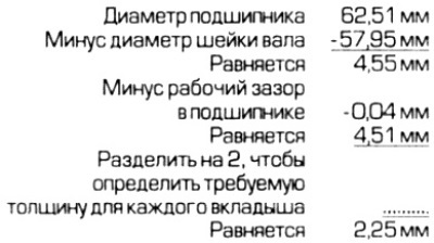
1. To determine the thickness of the required liners. the diameter of the shaft journals and the working clearance in the bearings should be determined. The required thickness can be calculated as shown in the example.
2. If it is determined that different thickness top and bottom bushings are required, the thicker bushing should always be fitted to the bearing cap.
3. Mercedes-Benz dealers or engine rebuilders can supply liners of the required thickness. Refer to the following table showing which earbuds are available.

Six cylinder petrol engines
4. The thickness of the required liners can be determined in the same way as previously described for 4-cylinder petrol engines. At the time of this writing, there was no information on the production liners for 6-cylinder gasoline engines. You can consult with Mercedes-Benz dealers. You can also buy liners from them.
Diesel engines
5. Earbuds are color coded. The earbuds are available in three thicknesses, identified by blue, yellow and red.
6. Color marking is applied to the crankshaft or on the cheeks of the shaft or on the counterweights after the necks. Marks are also applied to the cylinder block - they are in the form of recesses on the surface of contact with the pallet, behind the location of the bearings.
7. To limit the need to measure running clearance in bearings, select the correct insert according to the table below.
Crankshaft color code
Holes on the cylinder block

8 You can determine the thickness of the liners using the method described for a 4-cylinder gasoline engine. Refer to the table in item 3 to determine which bearing shells are available.
Checking the operating clearance in the main bearings
9. Working clearance can be determined by using "relatives" liners. However, it is more preferable to use a new set, since the results obtained will be more reliable.
10. Clean the back side of the liners and the seats on the cylinder block and main bearing caps.
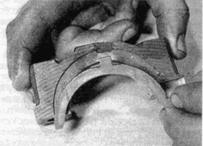
11. Install the liners in their places, making sure that the protrusion of the liner lies in the recess of the socket on the cylinder block or bearing cap. Do not touch the surface of the earbuds with your fingers. Note that grooved liners are installed on the cylinder block, and flat liners are installed on the covers. If used for verification "native" liners, make sure they are in place.
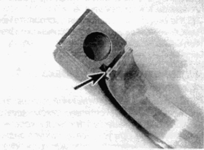
Pic. 19.11. Make sure the protrusion of the liner (shown by arrow) installed in a recess in the lid
12. The gap can be checked in two ways.
13. One way (which is difficult to implement without the use of an inside micrometer or caliper] is that with the bearings installed and the main bearing cap correctly tightened, the inner diameter of each assembled pair of bearings is measured. The operating clearance in bearings is defined as the difference between the inner diameter of the bearing and the outer diameter of the main journal.
14. Second (and more accurate) the method consists in the use of a plastic indicator ("Rastigauge"). The indicator is a thin plastic thread of a perfectly round shape, which is crushed between the main bearing and the neck. When the liners are removed, using a special template attached to the set, you can determine the working gap from the width of the pressed plastic strip. "Plastigauge" can be purchased from a Peugeot dealer (or order a similar product under a different name). The method is as follows.
15. Install the upper liners in bed and carefully install the crankshaft on them. Do not use lubricant; The crankshaft journals and liners must be perfectly clean and dry.
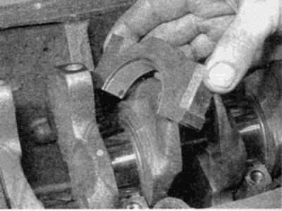
16. Cut a few pieces of Plastigage thread to the appropriate length (slightly shorter than the width of the inserts) and lay along the axis one piece of thread on each main journal of the crankshaft (see fig. 19.16)
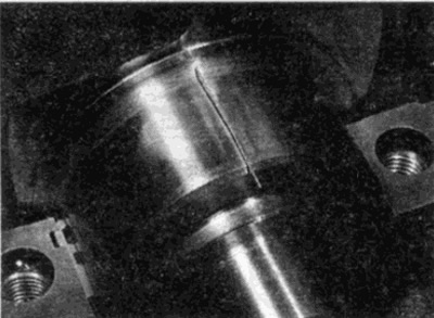
Pic. 19.16. Plastigauge thread on the crankshaft main journal
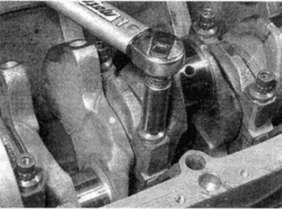
17. Insert the bushing into the bearing cover and install the cover in place, tightening it with bolts. Starting with the middle bearing and moving towards the periphery, gradually tighten the bearing cap bolts to the required torque. Do not move the Plastigauge thread or turn the crankshaft during this procedure.
18. Remove the bearing cap, do not move the Plastigauge thread again and do not turn the crankshaft. Again, be careful not to move the Plastigauge thread or rotate the crankshaft. If any of the covers is difficult to remove, tap it with a wooden mallet.
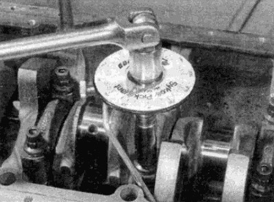
19. To determine the operating clearance in the bearing, compare the width of the Plastigauge strip on the neck with the template scale (see fig. 19.19). Compare your result with "technical data" at the beginning of this chapter.
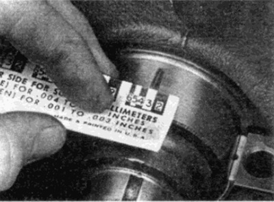
Pic. 19.19. Determination of the thickness of the deformed Plastigauge thread using a template
20. If the gaps are significantly different than expected, this means that the size of the liners is not selected correctly (or the liners are badly worn if used "native" liners). Before changing the size of the liners, make sure that no oil, dust, etc. gets between the liners. If the Plastigauge is not of uniform thickness, this may indicate a taper on the main journal.
21. If the gap does not meet specifications, determine the group of liners you need. When determining the required clearance, keep in mind that it is always better to get a clearance closer to the lower limit of the allowable range.
22. If necessary, purchase bearings of the correct size and repeat the operating clearance check as described above.
23. At the end of the measurement, scrape off all traces of Plastigauge with a fingernail, wooden or plastic scraper.
Final installation of the crankshaft
Note: It is strongly recommended that new main bearing cap bolts be used when finalizing the crankshaft. Sealant may be required when installing the rear crankshaft seal housing.
24. Carefully remove the crankshaft from the cylinder block.
25. Where installed, check that the oil spray tube nozzles are installed at the location of the bearings in the cylinder block.
26. Put the earbuds in place as described earlier. When installing new liners, wash off all traces of preservation with kerosene. Wipe the earbuds dry with a lint-free cloth. Liberally lubricate each bearing in the cylinder block with fresh engine oil.
27. Install the upper half rings on the corresponding bearing in the same way.
- A) 4-cylinder engines - medium (№3) main bearing
- b) 5-cylinder engine - #4 main bearing
- V) 6-cylinder engines - #5 main bearing
Make sure that all oil grooves in the thrust washers face the crankshaft journals.
28. Reinstall the crankshaft.
29. Lubricate the lower shells in the main bearing caps with clean engine oil. Check that the tabs in the bushings fit into the grooves in the covers.
30. Reinstall the main bearing caps, making sure they are correctly oriented. Check that the thrust washers are installed on the correct bearings (see par. 27) (see fig. 19.30, a, b).
Pic. 19.30 a.m. Installing the thrust half ring on the main bearing cap (apply some lubricant to keep the half ring on the lid)
Pic. 19.30 b. Installing the main bearing cap
31. Lightly lubricate the bolt threads, then install the cap bolts, using new bolts if possible (see paragraph 16 - it is strongly recommended to use new bolts on all engines). Where provided, check that the oil pickup tube bracket is in the correct location on the appropriate bolt as noted prior to removal. At this stage, tighten the bolts by hand.
32. Gradually tighten the bearing cap bolts to the required torque, starting at and working out from the middle bearing cap. Where provided, follow the tightening steps given in the Technical data section (see fig. 19.32, a, b). When tightening bolts to a certain angle, it is recommended to use an angle measuring device to improve tightening accuracy. If an angle gauge is not available, apply white paint alignment marks on the bolt and cover, they will allow you to determine the angle to which the bolts are tightened.
Pic. 19.32, a. Wrap bolts of fastening of covers of radical bearings with the demanded moment of an inhaling...
Pic. 19.32 b....then tighten to the desired angle
33. Check that the crankshaft turns freely.
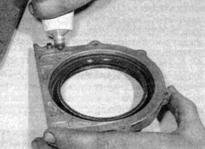
34. Install a new crankshaft rear seal into the housing, then install the housing using a new gasket or sealant (see fig. 19.34, a, b).
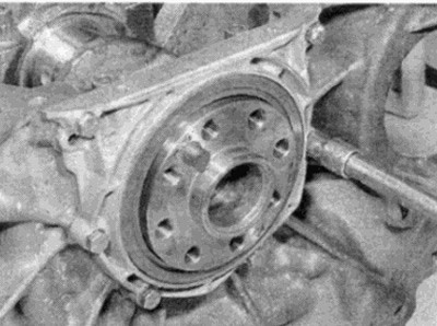
Pic. 19.34, a. Apply sealant to rear cuff housing
Pic. 19.34, b. Tighten with the required moment bolts of the case of a back cuff of a cranked shaft
35. Install the connecting rod and piston assemblies as described in paragraph 20.
36. Depending on the type of engine, perform the following steps.
- A) On 4-cylinder gasoline engines, where provided, install the crankshaft sprocket, then install the chain, chain case, sump and flywheel/drive plate as described in Part A of this Chapter.
- b) On 6-cylinder gasoline engines, where required, install the crankshaft sprocket, then install the chain, lower chain case, sump and flywheel/drive plate as described in Part B of this Chapter.
- V) On diesel engines, where required, install the crankshaft sprocket, then install the chain, chain case, oil pump, oil slinger plate (where provided), sump and flywheel/drive plate as described in parts of this chapter.