

Pic. 2.62. Measuring the width of the main bearing journal.
2. Lubricate the upper clearance adjusters with oil and install them in the cylinder block. Two lubrication channels (arrows) on the regulators should be directed towards the cheeks of the crankshaft (see fig.2.63).
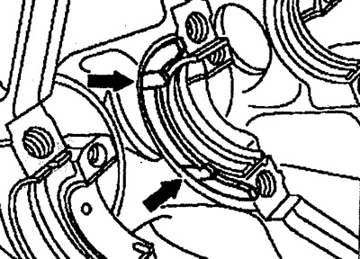
Pic. 2.63. The location of the upper axial clearance adjusters in the cylinder block.
3. Lubricate the lower clearance adjusters with oil and install them into the grooves in the main bearing caps. Both lubrication channels (arrows) should be directed towards the cheeks of the crankshaft (see fig.2.64).
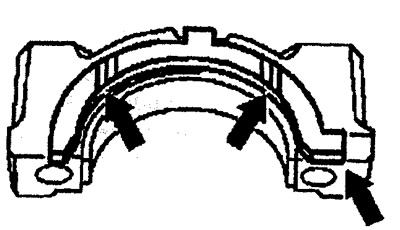
Pic. 2.64. The location of the lower axial clearance adjusters in the cylinder block.
4. Lubricate the crankshaft and install it. Install the main bearing shells according to the marks on them. Lubricate the bolts securing the main bearing caps with oil and tighten them to a torque of 55 Nm + 90° (see fig.2.65).
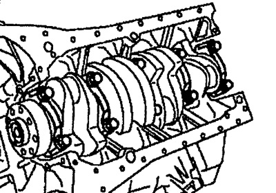
Pic. 2.65. Installing the crankshaft.
5. Measure the axial clearance in the crankshaft bearings (see fig.2.66). If the obtained value is determined within tolerance, correct the axial clearance by setting the axial clearance adjusters of the required thickness.
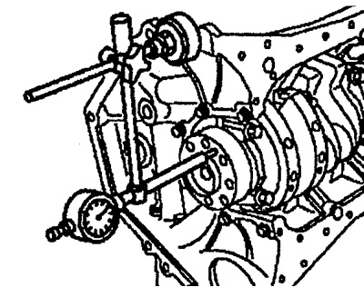
Pic. 2.66. Checking the axial clearance in the crankshaft bearings. (page 107)
6. Turn the crankshaft by hand and check for ease of rotation. Also check that the inserts are installed correctly (matching oil channels).