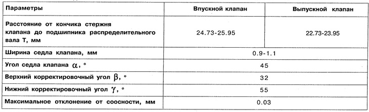
2. Grind the valve seats. Measure the valve seat width and adjust if necessary (angles a and P) (see figure 2.49).
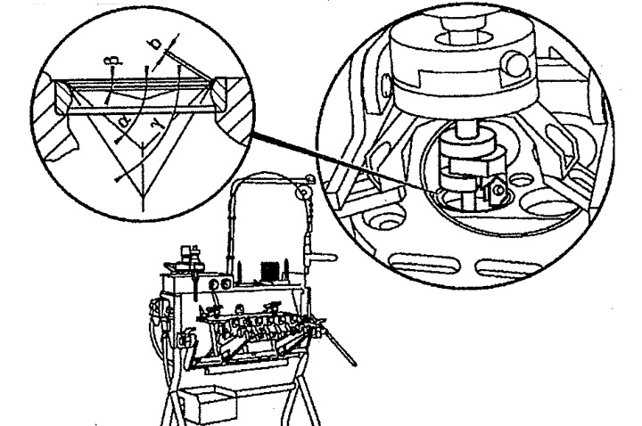
Figure 2.49. Valve seat angles.
b. Valve seat width,
α Valve seat angle,
β Upper correction angle,
γ Lower correction angle.
3. Measure the distance from the tip of the valve stem to the camshaft bearing (distance T) (see figure 2.50). To do this, insert a round tube into the hole for the camshaft bearing and measure the distance T. If the measured value without adjusting the valve clearance is less than required, replace the valve seat ring or cylinder head.
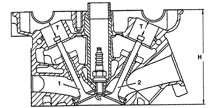
Figure 2.50. Checking the distance from the tip of the valve stem to the camshaft bearing.
1. Exhaust valve,
2. Inlet valve.
H. Cylinder head height.
T. Distance from the tip of the valve stem to the camshaft bearing.
4. Install all removed components in the reverse order of removal.
The valve seat angles are given in the table. 2.1.