
Note. The following procedure describes the procedures performed on a monthly basis. For other fluid level checks, see the appropriate Service Specific Sections below. Regardless of the intervals stipulated by the Schedule, try not to disregard the occurrence of fluid leaks under cars - such signs indicate the presence of malfunctions that must be immediately eliminated.
Attention! When checking the level of any working fluid, the car must be located strictly horizontally!
Fluids are an integral part of lubrication, cooling, braking and windshield washing systems. Due to the normal consumption and tendency to contamination during the operation of the vehicle, it is necessary to periodically check the condition / levels and replace the working fluids - read the requirements Specifications to the types of compositions used and the filling volumes of the respective systems.
Engine oil
Visual control of leaks
1. With noticeable oiling of the power unit and high oil consumption, carefully inspect the places where leaks are most likely to develop:
- The sealing element of the engine oil filler cap, - check for cracks and other mechanical damage;
- Components of the crankcase ventilation system (in particular - the ventilation hose from the cylinder head cover to the intake duct);
- cover gasket (ek) cylinder heads;
- head gasket (OK) cylinders;
- Sealing element of the drain plug of the engine crankcase;
- Oil filter gasket, - carefully examine the place where the filter fits on the mounting flange;
- Oil pan gasket;
- Front and rear crankshaft seals.
2. Wrap the generator in polyethylene, spray the engine with a normal cold cleaner, - then, after a short time - wash the unit in a car wash.
3. Sprinkle the joints of the mating surfaces and the sealing elements of the power unit with lime or talc from the outside.
4. Check oil level, correct if necessary (see below).
5. During the short (about 30 km) travel (preferably on the highway) warm up the engine to normal operating temperature - hot oil is characterized by increased fluidity and seeps through leaks more easily.
6. Park the car in a safe place and, highlighting yourself with a lamp, examine the engine in order to localize sources of oil leaks. Eliminate the causes of the development of leaks.
Level check
Note. The maximum allowable consumption of engine oil is 1 l/1000 km, the actual level of oil consumption depends on the driving style - frequent driving at high engine speeds leads to an increase in oil consumption.
1. The function of monitoring the level of impellent oil is included in Section «Standard display» on-board computer main menu (refer to the vehicle owner's manual, - ask in automotive literature stores).
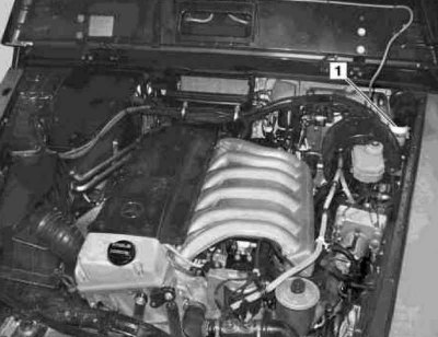
2. A physical check of the oil level is made using a dipstick threaded into the guide tube and lowered into the engine to the bottom of the oil pan of its crankcase (see illustrations Engine compartment of petrol models (on the example of the G55 AMG), Engine compartment of G270 CDI diesel models and Engine compartment for G400 CDI diesel models). The oil level should be checked before the first trip of the day, or about 5 minutes after the engine has been stopped. If the test is performed immediately after the engine is turned off, the results will not adequately reflect the situation, since some of the oil will be distributed over the internal galleries and engine components.
3. Remove the dipstick from the guide tube and dry its blade with a clean cloth or paper towel. Insert the dipstick back into the tube until it stops, then remove it again. After examining the probe blade, estimate the size of the area wetted with oil. The oil level should be between the upper and lower marks on the dipstick blade. If necessary, top up the engine with the appropriate amount of oil of the required grade.
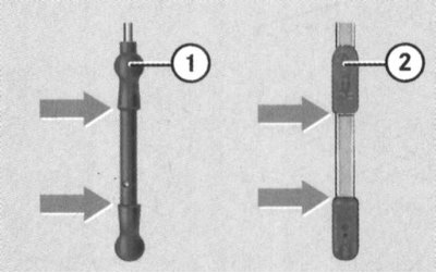
1 - The design of the blade of the measuring probe used on the G320/500/55 AMG/400 CDI models
2 - Probe blade design used on G270 CDI models
Note. In order to raise the level from the bottom mark on the dipstick blade to the top mark, about 2 liters of oil are required.
4. Lowering the level beyond the lower limit of the permissible range leads to the development of engine oil starvation and is fraught with serious mechanical damage to the latter. Try also not to overfill the oil above the upper mark, as this can lead to throwing spark plugs or failure of the power unit seals as a result of excessive pressure buildup.
5. In order to fill the engine with oil, it is necessary to remove the threaded filler cap (see illustrations Engine compartment of petrol models (on the example of the G55 AMG), Engine compartment of G270 CDI diesel models and Engine compartment for G400 CDI diesel models). Use a funnel or an oil can with a long spout to avoid splashing oil when filling it into the engine. After filling in oil, screw on and firmly tighten the filler cap, then start the engine and carefully inspect the drain plug and the surface of the oil filter mating with the block for signs of leakage. Stop the engine, wait 5-10 minutes for the oil to drain into the sump, then check the level again.
Note. Excess oil must be drained or pumped out of the crankcase - an excessive level of impellent oil can cause failure of the catalytic converter. Track reliability of a tightening of a cover of a jellied mouth.
6. Checking the engine oil level is an important preventative engine maintenance procedure. A constantly low level indicates the presence of oil leaks as a result of failed oil seals, damaged seals, worn piston rings or valve guides. If the oil resembles milk in color or consistency, or there are drops of water in it, this indicates a possible damage to the cylinder head gasket, or the formation of cracks in the body of the head (OK) or block. The check must be made without delay. When measuring the oil level, always also check its condition. Using your thumb and forefinger, remove traces of oil from the dipstick blade - if there are small metal particles in it, the oil must be replaced (see Section Changing the engine oil and oil filter).
Engine coolant
Attention! Do not allow antifreeze to come into contact with exposed areas of the body and painted surfaces of the car. Wash off accidental splashes with plenty of water without delay. Remember that antifreeze is a highly toxic liquid and getting it into the body, even in small quantities, is fraught with the most serious consequences, even death. Never leave antifreeze stored in a loosely closed container, immediately collect spilled coolant on the floor. Remember that the sweet smell of antifreeze can attract the attention of children and animals. Consult with local authorities about ways to dispose of used coolant - in many regions of the world there are special points for receiving various kinds of waste. Never drain old coolant down the drain and onto the ground!
Note. Recently, non-toxic grades of antifreeze have been developed, however, they must also be disposed of in an organized manner.
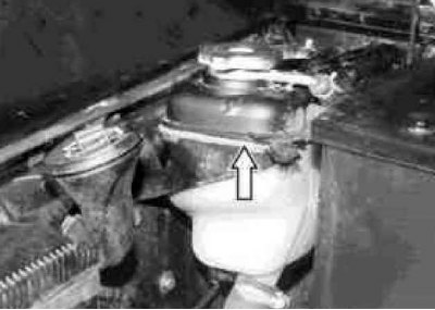
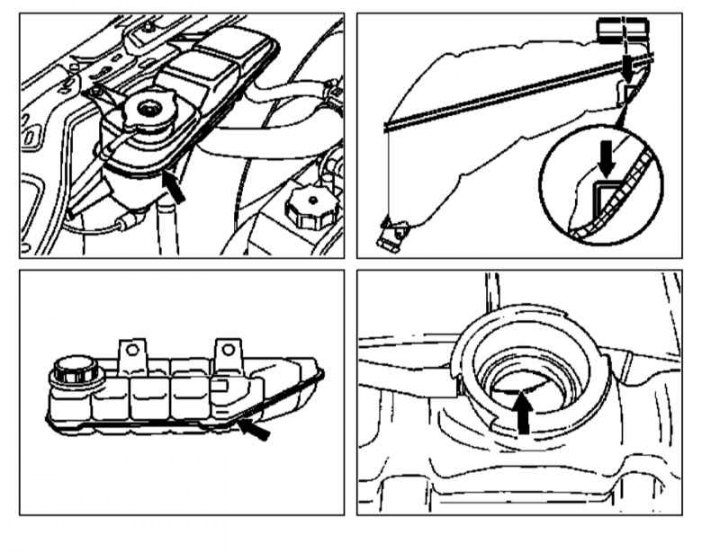
1. All vehicles covered in this manual are equipped with an overpressure compensation type cooling system. The plastic expansion tank is located on the right in the engine compartment and is connected by hoses to the radiator and the water jacket of the power unit (see illustration Engine compartment of petrol models (on the example of the G55 AMG)). As the engine warms up during operation, the expanding coolant fills the reservoir. When the engine cools down, the coolant automatically flows back into the cooling system, which maintains a constant value of its level.
2. Checking the coolant level in the tank should be done regularly, with the vehicle in a strictly horizontal position and the engine off. When cold, the coolant level must reach the reference mark on the wall/inside of the expansion tank, depending on the version. After the engine warms up, the coolant level rises by about 1.0-1.5 cm. If necessary, make the appropriate adjustment - add only the liquid of the required composition (see Specifications).
3. Having made a short trip on the car, measure the coolant level again, a slight adjustment can be made by adding distilled water, however, it should be remembered that frequent additions of water lead to dilution of antifreeze, so it is wiser to always add a mixture of the required composition to the system.
4. The regular need to adjust the coolant level indicates the presence of its leaks (external or internal), - carefully examine the external condition of the radiator, connecting hoses, filler cap, drain plugs and water pump (see Section Checking the functioning of the cooling system and frost resistance of the coolant, changing the fluid). If it is not possible to identify the source of the leak, check the tightness of the caps of the expansion tank and radiator in a workshop.
5. Removing the covers of the components of the cooling system should be done after the engine has completely cooled down. Wrap the cover with a rag and unscrew it to the first point of weakening of resistance - if steam or coolant begins to escape from under the cover, let the engine cool a little more, and only then remove the cover completely.
6. It is also necessary to check the condition of the coolant, it must be relatively clean. If the liquid has a reddish-brown color, it must be drained, then the cooling system path must be flushed and filled with a fresh mixture of the required composition. Even if the coolant looks normal, the corrosion inhibitors included in its composition lose their effectiveness over time, therefore, in any case, replacement should be carried out in accordance with Schedule of ongoing maintenance.
7. If necessary, a check of the resistance of the coolant to freezing can be carried out using a hydrometer - compare the measurement results with the requirements Specifications.
Coolant level checkpoint inside expansion tank (checked through the neck)
Brake fluid
Attention! When servicing the hydraulic path of the brake system, be extremely careful. Do not allow brake fluid to get into your eyes, mouth or painted surfaces of the vehicle! Remember that brake fluid is highly hygroscopic, i. has the ability to absorb moisture contained in the air - in no case add hydraulic fluid to the brake system that has been stored for a long time in a loosely closed container! Use only recommended types of brake fluid - mixing different types of fluid can lead to brake system failure!
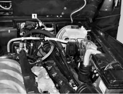
1. Reservoir brake master cylinder (GTZ) system is installed in the rear left corner of the engine compartment. A drop in the driver's brake fluid level is warned by the operation of a warning lamp built into the instrument cluster (see Section Instrument cluster, meters, control lamps and indicator lights), whose float switch is built into the cover (release models before 12.2000) /frame (release models since 12.2000) GTC tank.
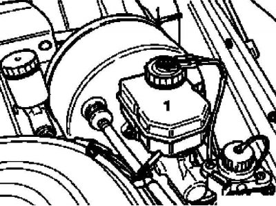
a - Location of the tank equipped (1) brake master cylinder on models up to 12.2000 | 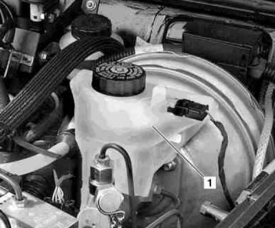
b — Location of tank-equipped (1) brake master cylinder on models from 12.2000 |
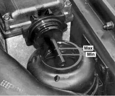
2. The brake fluid level is checked visually and must be between the marks «MAX» And «MIN», applied to the translucent walls of the GTZ tank. If necessary, make the appropriate adjustment by adding the required amount of fresh fluid through the reservoir neck - before unscrewing the cover, wipe the reservoir from the outside to prevent dirt from entering the hydraulic path.
Note. Do not overfill the tank with liquid.
3. With the cover removed, check the liquid and the walls of the GTZ reservoir for signs of contamination. If the presence of rust particles, dirt or water drops is detected, the fluid should be replaced and then «pumping» brake system (see chapter Brake and auxiliary systems).
4. After completing the adjustment/replacement, check that the reservoir cap is even and tight.
5. The gradual lowering of the liquid level in the GTZ reservoir is due to the wear of the brake pads. There is no need to add liquid if its level does not fall below the mark «MIN», - if necessary, check the condition of the friction linings of the brake pads, - replacing the pads will automatically equalize the level.
6. If the need to adjust the brake fluid level occurs regularly, you should immediately carefully check the hydraulic path of the brake system for signs of leaks, - carefully examine the condition of the calipers / wheel cylinders, GTZ, brake pipes, hoses and their union connections, (see Sections Checking the brake system and Checking the condition and replacing the engine compartment hoses, localizing leaks).
7. When the liquid level in the GTZ tank drops below the mark «MIN» brake system should «pump» (see chapter Brake and auxiliary systems).
Power steering fluid (power steering)
Attention! If the fluid level in the power steering reservoir has dropped below the zone corresponding to the current temperature range, the condition of the power steering must be checked at a Mercedes-Benz branded service station - a simple level adjustment in this case will not be enough.
Note. As part of the scheduled maintenance procedures, the power steering fluid level is not monitored.
1. Checking the power steering fluid level is carried out at a temperature of about 20°C. The power steering reservoir is equipped with a screw cap equipped with a measuring probe and is placed on the right in the engine compartment (see illustration Engine compartment of petrol models (on the example of the G55 AMG) and accompanying illustrations). On diesel models, the cylinder head trim panel must be removed to gain access to the power steering reservoir. The fluid level must be between the marks «MIN» And «MAX» on the stylus blade.
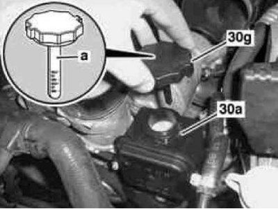
a - Location of the power steering reservoir on gasoline models
30a - Power Steering Reservoir
30g - Power Steering Reservoir Cap
a - GUR liquid level probe
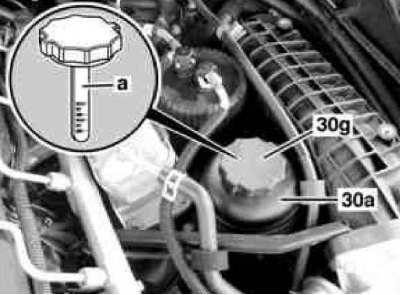
b - Location of the power steering reservoir on diesel models equipped with an M612 engine
30a - Power Steering Reservoir
30g - Power Steering Reservoir Cap
a - GUR liquid level probe
c - Location of the power steering reservoir on diesel models equipped with the M628 engine
Differential Lock Fluid
Attention! The hydraulic circuit of the differential lock actuator uses brake fluid, which must be handled with special precautions (see the warning above in the relevant subsection).
Note. As part of the scheduled maintenance procedures, the fluid level of the differential lock hydraulic drive is not monitored.
1. The location of the differential lock hydraulic reservoir is shown in the illustration Engine compartment of petrol models (on the example of the G55 AMG) and accompanying illustrations.
A — Location of the tank (1) differential lock hydraulic drive on production models up to 12.2000.
b — Location of the tank (1) differential lock hydraulic drive on production models from 12.2000
2. The liquid level should be slightly above the MAX mark applied to the translucent tank wall - if necessary, make the appropriate adjustment by first checking the hydraulic drive hydraulic path for signs of leakage development and eliminating the causes of the latter.
Transmission fluid (ATF)
Note. The automatic transmissions used on the considered car models are filled with transmission fluid for the entire service life and do not need regular checks and level adjustments.
ATF level check
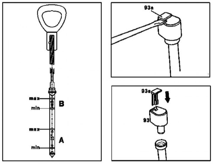
93a - Locking latch
93 - Cover
A - 25°С
B - 80°С
1. It is best to check the ATF level when the engine and transmission are warm - take a short (about 15 km) trip.
2. Park the vehicle on a level surface and apply the parking brake. To securely fix the vehicle, support the wheels with wheel chocks.
3. Run the engine to idle. Depress the foot brake pedal and carefully shift the selector lever from the position «R» into position «D», then return it. Check for signs of developing external ATF leaks.
4. The fluid level dipstick is located at the rear of the transmission. Before removing the dipstick, carefully wipe the surface of the crankcase adjacent to the crankcase - the ingress of dirt into the transmission is unacceptable.
5. Using a suitable screwdriver, pry out the locking latch (the red tab of the latch breaks off, and the remaining fragment is pushed out of the cover down) and remove the cover (see illustration above).
6. Start the engine and, holding the vehicle motionless with the foot brake, sequentially move the selector lever through all operating ranges, finally returning it to the position «R».
7. After thoroughly wiping, fill the dipstick all the way into the transmission filler neck. Remove the dipstick and determine the ATF level in the transmission housing by the length of the wetted area of its blade; when the unit is cold, the level should be between the min and max marks of the lower (25°C) probe scale, when hot - between identical marks on the top (80°) scales (see illustration above).
8. During a short drive, warm up the transmission to normal operating temperature, wait about 2 minutes, and check the fluid level again with the engine running. If the ATF level is excessively high, the excess fluid must be pumped out of the AT crankcase without fail - exceeding the level, as well as a lack of ATF, can lead to transmission failure.
9. Replace the filler cap and lock it with the new locking clip (see illustration above).
10. Carefully inspect the AT crankcase for signs of leak development, if necessary, make the necessary corrections.
Transfer Case Lubricant
Note. As part of the scheduled maintenance procedures, the oil level in the transfer case is not monitored.
1. Make sure the vehicle is level. Wipe the surface of the transfer case housing around the filler/check plug (see resist. Illustration - The location of the filler / control plug on the crankcase of the transfer case series 750.65).
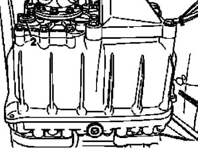
2. Unscrew the plug and, inserting a finger into the hole, check the oil level in the crankcase - it should reach exactly to the lower cut of the hole. Make appropriate adjustments if necessary.
Windshield/Headlight Washer
Attention! Windshield washer concentrate is highly flammable! Do not use fire, open flames or smoking when handling windshield washer concentrate.
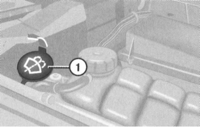
1. The windshield washer fluid reservoir is installed in the right rear corner of the engine compartment, behind the expansion tank of the cooling system and is equipped with a filler neck with a bayonet-type cap (see resist. Illustration - Location of the windscreen/headlight washer fluid reservoir in the engine compartment (for all models)). The capacity of the tank is about 7.5 liters (see Specifications).
2. A warning lamp built into the instrument cluster warns of a drop in the driver's fluid level, - the control lamp sensor-switch is mounted in the upper part of the washer fluid reservoir.
3. In temperate regions, the system can be filled with ordinary water, but it is recommended to add glass cleaner to the water (summer MW concentrate is labeled S). The tank should be no more than two-thirds full, so that there is free space in case the water expands when it freezes. In areas with cold climates, a special glass washer concentrate should be used (W marking), which lowers the freezing point of the liquid, which can be purchased at any auto accessories store. It is usually sold in concentrated or prepared form. Mixing the concentrate with water should be carried out strictly in accordance with the manufacturer's instructions on the package.
Attention! In no case do not use antifreeze of the cooling system to wash the windows, which can damage the paintwork if it gets on the body panels!