
Removing
Note: This job requires a hoist and winch.
1. Remove the gearbox as described in Chapter 7.
2. Where required, remove the motor shield from below as described in Chapter 11.
3. Drain the oil and coolant from the engine as described in Chapter 1A.
4. Remove the air cleaner as described in Chapter 4.
5. Remove the heatsink and heatsink fan as described in Chapter 3.
6. On models with air conditioning, place a large sheet of cardboard in front of the air conditioning condenser to protect it from damage during further operations.
7. Where provided, loosen the union nuts and disconnect the hydraulic lines from the suspension leveling pump located in front of the cylinder head (see fig. 4.7). Prepare to spill liquid and plug the open ends of the pump and tubing.
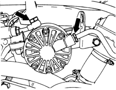
Pic. 4.7. Disconnect hydraulic pipes (shown by arrows) from suspension leveling pump
8. On models equipped with an air conditioning system, remove the accessory drive belt as described in Chapter 1 and disconnect the plug from the compressor.
9. Turn away bolts and remove parts of a belt tensioner forward from the engine. Note the location and orientation of all parts so you can reinstall them correctly (see fig. 4.9, a, b, c).
- A) On models without a hydraulic shock absorber strut, unscrew the mounting bolt and remove the tensioner.
- b) On models with a hydraulic shock absorber strut located below the tensioner, remove the strut lower end bolt and the two tensioner bracket bolts, then remove the bolt in the center of the tensioner and remove the parts.
- V) On models with a hydraulic shock absorber strut located above the tensioner, unscrew the power steering pump pulley, then unscrew the tensioner pulley. Unscrew the end of the strut from the tensioner bracket, if necessary, holding the bolt from turning with an open end wrench. Remove the strut strut bolts from the alternator support bracket and remove the washer where provided. Hold the bolt securing the tensioner to the power steering pump bracket and remove the nut from the bottom of the bracket. Remove the two bolts securing the tensioner bracket to the camshaft timing chain case. Remove the bolt from the center of the tensioner and remove the tensioner together with the bracket.
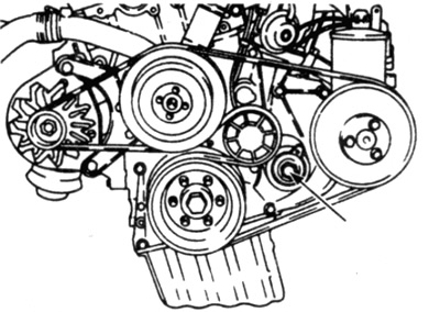
Pic. 4.9, a. Loosen the mounting bolt (shown by arrow) and remove the accessory drive belt tensioner - models without suspension strut
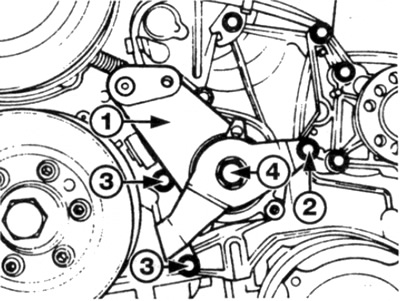
Pic. 4.9, c. Accessory Drive Belt Tensioner Parts - Models with Shock Absorber Above Tensioner
1 Tensioner
2 Tensioner mount to power steering pump bracket
3 Bolts securing the tensioner bracket to the camshaft drive chain cover
4 Central tensioner bolt
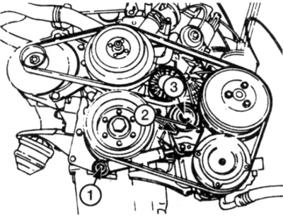
Pic. 4.9b. Accessory Drive Belt Tensioner Parts - Models with Shock Absorber Below the Tensioner
1 Lower suspension strut mounting bolt
2 Tensioner bracket bolts
3 Central tensioner mounting bolt
10. Turn away a pulley of the pump of system of the hydraulic booster of a steering.
11. Remove the rear bracket bolts on the power steering pump, air conditioning compressor (where it is installed) and cylinder block. Remove bracket from engine (see fig. 4.11).
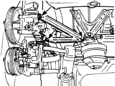
Pic. 4.11. Bolts of fastening of a back arm of the pump of the power steering / compressor of the air conditioner
12. Turn away bolts of the pump of the hydraulic booster of a steering (see chapter 10) and take it aside without disconnecting the hydraulic pipes.
13. Similarly, on air-conditioned models, remove the compressor bolts (if necessary, contact Chapter 3) and move it to the side without disconnecting the cooling tubes.
14. Where provided, remove the bracket bolts and release the tube/hose assembly from the front left corner of the cylinder head.
15. Disconnect the generator wire.
16. Working in the engine compartment, disconnect the wires from the relevant parts and connectors. Remember the location and routing of all connections so as not to confuse during installation. Loosen the bolts or unfasten the holders of all wires and wiring harnesses on the engine.
17. Similarly, disconnect all vacuum lines, noting their location and how they are routed.
18. Disconnect the throttle cable from the throttle control lever (if necessary, refer to Chapter 4). then release the cable from all brackets on the engine and move to one side.
19. On models with fuel injection, depressurize the fuel system as described in Chapter 4B.
20. Where provided, remove the union nuts, then disconnect the supply and return lines from the carburetor/fuel distributor/pressure regulator. Where necessary, hold the fitting. Prepare to collect spilled fuel by plugging open ends of fuel lines and fittings.
21. Disconnect the heater hose from the left rear corner of the cylinder head.
22. Turn away the union and disconnect a vacuum hose of the hydraulic booster of a steering from an inlet collector.
23. If not already, attach the hoist and winch to the rigging brackets on the cylinder head and adjust the winch to support the engine. Note that the hoist must be able to lift the engine high enough to separate it from the vehicle.
24. Insert a sheet of cardboard between the rear of the cylinder head and the bulkhead to protect the bulkhead when the engine is raised (see fig. 4.24).
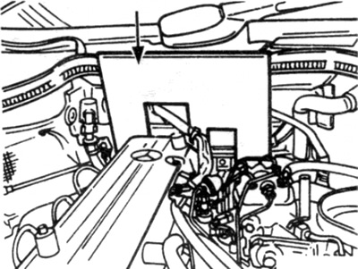
Pic. 4.24. Insert a sheet of cardboard (shown by arrow) on the back of the engine
25. Finally check that all required hoses, tubes and wires are disconnected and do not interfere with engine removal.
26. If not already done, remove the two lower engine mount bolts. Where provided, also unscrew the strut damper on the left side of the vehicle.
27. Raise the hoist and, if necessary, adjust the winch to raise the engine vertically.
28. Slowly lift the assembly up and take care not to damage the surrounding parts in the engine compartment.
Installation
29. Installation is carried out in the reverse order. Consider the following points.
- A) Where required, tighten all fasteners to the correct torque.
- b) Make sure all wires, hoses. pipes and brackets are installed and routed as they were before.
- V) Connect and, if necessary, adjust the throttle cable as described in Chapter 4.
- G) Where required, install the accessory drive belt as described in Chapter 1.
- d) Install the heatsink and heatsink fan as described in Chapter 3.
- e) Install the gearbox as described in Chapter 7.
- and) When finished, fill the engine with oil and fill the cooling system as described in Chapter 1A.