
Attention! A lifting mechanism must be used to remove the cylinder head. When installing the cylinder head, a new head gasket and a new intake camshaft bearing bolt must be used.
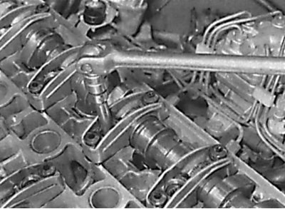
Loosening the cylinder head bolts
Removing
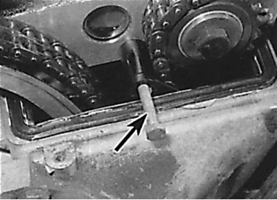
Screwing an additional bolt into the upper dowel pin of the chain guide
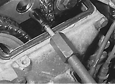
Using an inertia hammer to remove the top pin of the chain guide
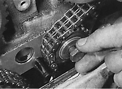
Removal of an intermediate asterisk of a driving chain
Removing the bearing from the front side of the camshaft
Removing the drive chain from the camshaft sprockets
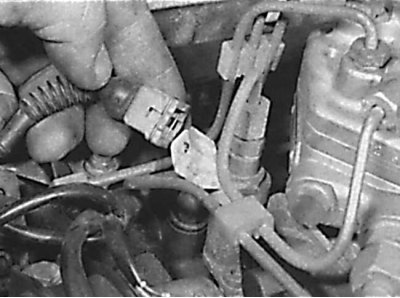
Disconnecting the electrical connector from the fuel injector
Disconnecting the electrical connector from the coolant temperature sensor on the 3.0L engine
Removing the ground bus from the intake manifold of the 3.0L engine
Location of wiring harness bracket on intake manifold of 3.0L engine
Disconnecting the vacuum hoses from the intake manifold
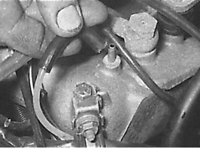
The location of the air pipe on the cylinder head
Air Valve Mounting Bracket Location
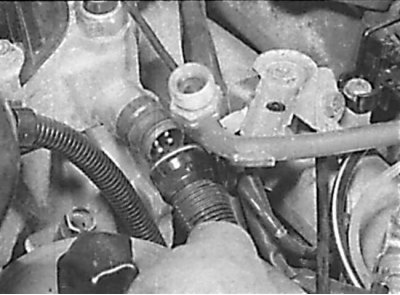
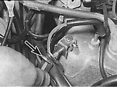
Unscrewing the fuel line from the pressure regulator on the 3.0L engine
Unscrewing the pipe mounting bracket for the dipstick for measuring the oil level
Unscrewing the pipe bolt for the dipstick for measuring the oil level in an automatic transmission
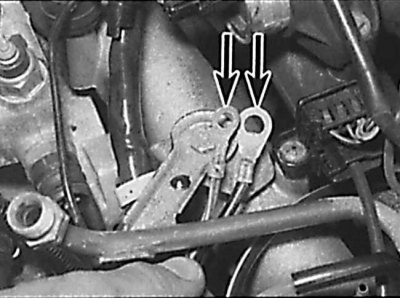
Location of intake manifold support bracket bolts
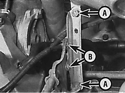
And – bolts of fastening of an arm;
B - pipe fixing bolts
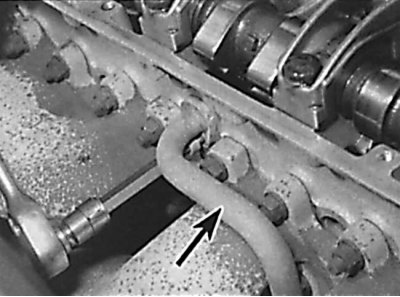
Location of crankcase ventilation hose
Removing the cylinder head from the engine
1. Removal of a head of the block of cylinders make on the cold engine. The cylinder head is removed along with the intake and exhaust manifolds.
2. Remove the ground wire from the battery.
3. Open the hood and place it in a vertical position.
4. Drain the coolant and remove the radiator.
5. Disconnect the coolant supply hose from the rear left side of the cylinder head.
6. Set the piston of the first cylinder to TDC and check that all the installation marks are aligned with the pointers.
7. Remove the top drive chain cover.
8. Apply alignment marks to the drive chain links and sprocket.
9. Screw an additional bolt into the upper dowel pin of the chain guide (see fig. Screwing an additional bolt into the upper dowel pin of the chain guide).
10. Using an inertia hammer and an adapter, use the additional bolt to remove the upper dowel pin of the chain guide (see fig. Using an inertia hammer to remove the top pin of the chain guide).
11. On 3.0L engines, remove the left-hand bolt and remove the drive chain intermediate sprocket (see fig. Removal of an intermediate asterisk of a driving chain).
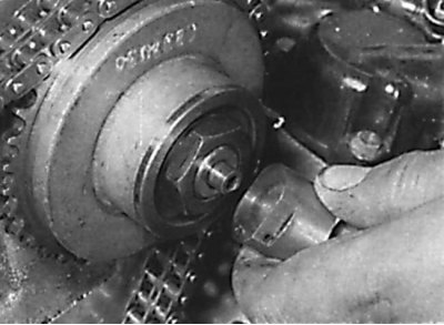
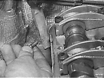
12. From the front of the intake camshaft, holding the bearing from turning, unscrew the bolt and remove the bearing (see fig. Removing the bearing from the front side of the camshaft).
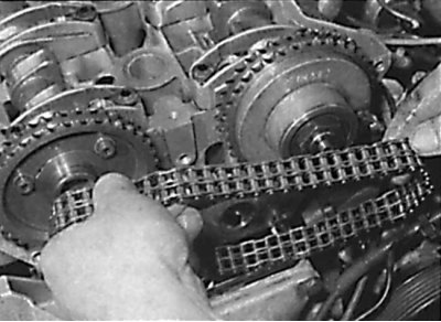
13. Remove the drive chain from the camshaft sprockets and, using a soft wire, secure it from falling into the cover (see fig. Removing the drive chain from the camshaft sprockets).
14. Disconnect all electrical connectors from the cylinder head. Unscrew the bolt securing the wiring harness bracket to the manifold and move the wiring harness to the side (see fig. Disconnecting the electrical connector from the fuel injector, Disconnecting the electrical connector from the coolant temperature sensor on the 3.0L engine, Disconnecting the ground strap from the intake manifold of the 3.0L engine, Location of the wiring harness bracket on the intake manifold of the 3.0L engine).
15. Disconnect the speed control link.
16. Mark the location and disconnect all vacuum hoses from the intake manifold (see fig. Disconnecting the vacuum hoses from the intake manifold).
17. Disconnect the exhaust pipe from the exhaust manifold.
18. Disconnect the air pipe from the cylinder head (see fig. The location of the air pipe on the cylinder head).
19. Unscrew the air valve mounting bracket and remove it together with the pipe from the engine (see fig. Air Valve Mounting Bracket Location).
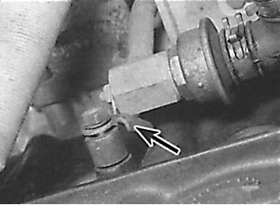
20. Depressurize the fuel system and unscrew the fuel supply and return lines (see fig. Unscrewing the fuel line from the pressure regulator on the 3.0L engine).
21. Remove the bolt securing the pipe bracket for the dipstick to measure the oil level. Remove the dipstick and remove the pipe from the cylinder block (see fig. Unscrewing the pipe mounting bracket for the dipstick for measuring the oil level).
22. Disconnect the accelerator cable from the throttle lever.
23. On automatic transmission models, disconnect the pressure control cable from the throttle linkage.
24. On models with an automatic transmission, unscrew the bolts securing the dipstick tube in the transmission from the rear of the cylinder head (see fig. Unscrewing the pipe bolt for the dipstick for measuring the oil level in an automatic transmission).
25. Unscrew and remove the two intake manifold support brackets (see fig. Location of intake manifold support bracket bolts).
26. From the back of the intake manifold, remove the clamp securing the vacuum hose and wiring harness.
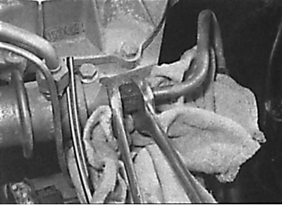
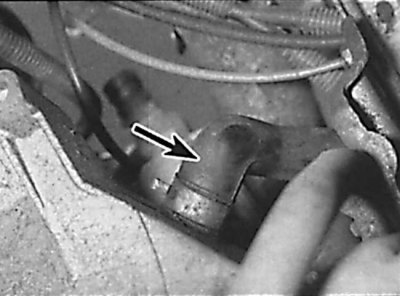
27. Loosen the clamp and remove the crankcase ventilation hose from the breather housing under the intake manifold (see fig. Location of crankcase ventilation hose).
28. Loosen the clamp and remove the coolant supply hose from the elbow on the front of the engine.
29. Check that all hoses and electrical connectors are disconnected from the cylinder head.
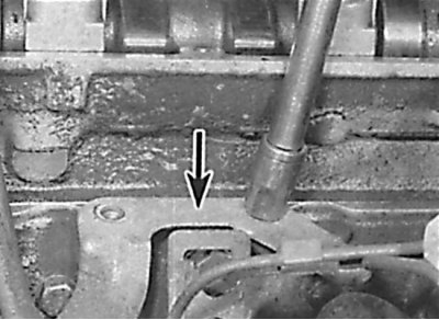
30. Evenly and gradually loosen and unscrew the cylinder head bolts in the reverse order shown in the figure Location of crankcase ventilation hose.
31. Screw the front engine lifting eye to the cylinder head.
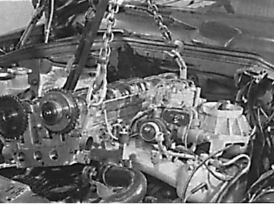
32. Using a lifting mechanism, remove the cylinder head (see fig. Removing the cylinder head from the engine).
33. Remove the cylinder head gasket.
Preparing for installation
1. The mating surfaces of the engine head and cylinder block must be thoroughly cleaned of gasket residue and carbon deposits using a plastic or wooden scraper. It is also necessary to clean the tops of the pistons. When cleaning, exclude the possibility of cleaning products getting into the oil channels of the cooling system. Thoroughly clean the inner surfaces of the cylinders.
2. Check the mating surfaces of the engine head and cylinder block for defects. Minor damage is eliminated by machining. Also, using a metal ruler and feeler gauge, check the flatness of the mating surfaces.
3. Clean the bolt holes in the block. Screwing a bolt into an oil-filled hole can rupture the block due to hydraulic pressure.
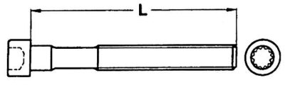
4. Measure the length of the cylinder head bolts (see fig. Preparing for installation). If the bolt length exceeds the allowable limits, replace the bolts as a set.
Installation
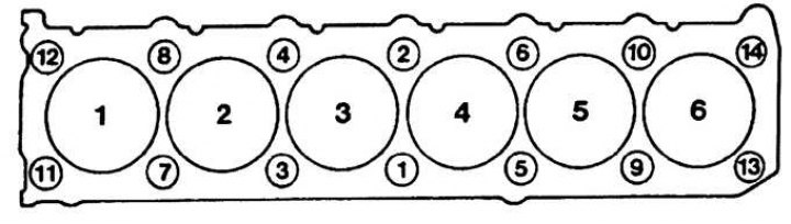
DOHC 6-cylinder head bolt tightening sequence
1. Check that the timing marks on the crankshaft and camshaft are aligned with the pointers.
2. Install the cylinder head gasket to the cylinder block guide pins.
3. Install the two cylinder head rear bolts.
4. Using a hoist, install the cylinder head to the engine.
5. Unscrew the bolts and remove the front eye to lift the engine from the cylinder head.
6. Lubricate the cylinder head bolts with engine oil and, being careful, insert them into their sockets. Tighten the head bolts by hand.
7. In the sequence shown in Figure 6-Cylinder DOHC Cylinder Head Bolt Tightening Sequence, tighten the cylinder head bolts in several steps.
8. Further installation is carried out in the reverse order of removal. Pour coolant into the cooling system.