
Exhaust camshaft sprocket
Removing
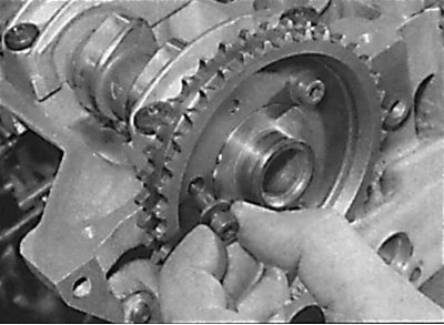
Unscrewing the bolts of the camshaft sprocket
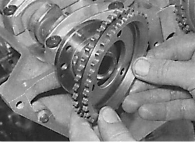
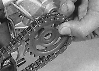
Removing the sprocket from the camshaft that controls the exhaust valves
1. Remove the cylinder head cover.
2. Rotate the engine until the 30°BDC mark on the crankshaft pulley is aligned with the side of the crank angle sensor bracket.
3. Remove the top drive chain cover.
4. Using paint, apply alignment marks to the drive chain link and sprocket, then unscrew the sprocket mounting bolts (see fig. Unscrewing the bolts of the camshaft sprocket). Fix the camshaft from turning with a wrench by the flats behind the fifth camshaft bearing cap.
5. Remove the sprocket from the camshaft (see fig. Removing the sprocket from the camshaft that controls the exhaust valves). Remove the key or dowel pin from the front end of the camshaft.
6. Remove the sprocket from the drive chain and secure the chain, keeping it in a permanently taut position.
Examination
1. Check the condition of the teeth on the sprocket. The teeth on the sprocket are symmetrical and if one side of the teeth is worn out, the sprocket must be replaced.
Installation
1. Check that the engine crankshaft is at 30°to top dead center on the #1 piston.
2. Install the key or dowel pin on the front end of the camshaft.
3. Install the sprocket in the chain, matching the previously made marks.
4. Install the sprocket on the camshaft and secure with bolts, tightening them to the required torque.
5. Install the upper chain guide and tensioner.
6. Install the cylinder head cover.
Camshaft sprocket controlling the intake valves
The removal and installation of the intake camshaft sprocket is part of the process of removing and installing the intake camshaft adjustment mechanism.
Intermediate shaft sprocket (engine 3.0)
Removing
Attention! The intermediate sprocket mounting bolt has a left-hand thread.
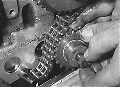
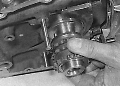
Removal of an intermediate asterisk of a driving chain
1. Remove the top drive chain cover.
2. Install a wrench on the camshaft flats behind the No. 5 bearing cap and turn the intake camshaft counterclockwise to loosen the drive chain tension on the intermediate sprocket.
3. To properly reinstall the sprocket, mark the outer end of the sprocket.
4. Unscrew the bolt securing the intermediate sprocket (left hand thread) remove the sprocket and bearing bush (see fig. Removal of an intermediate asterisk of a driving chain).
Examination
1. Check the condition of the teeth on the sprocket. The teeth on the sprocket are symmetrical and if one side of the teeth is worn out, the sprocket must be replaced.
Installation
1. Install the support bushing, intermediate sprocket and secure it with the bolt, tightening it to the required torque.
2. Use a wrench to turn the camshaft that controls the intake valves clockwise by the flats until the drive chain is tensioned on the intermediate sprocket.
3. Install the upper drive chain cover.
Crankshaft sprocket
Removing
Unscrewing the oil pump sprocket bolt
Removing the oil pump sprocket
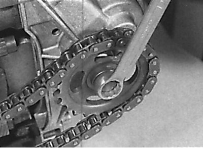
Removing the crankshaft sprocket
1. Remove the oil pan.
2. Remove the lower chain guide and tensioner shoe.
3. Make a mark on the front side of the oil pump sprocket, unscrew the bolt and remove the oil pump sprocket along with the chain (see fig. Unscrewing the oil pump sprocket bolt, Removing the oil pump sprocket).
4. Remove the oil pump drive chain tensioner shoe, spring and bushing from the pivot pin.
5. Put alignment marks on the drive chain link and crankshaft sprocket, and remove the drive chain from the sprocket.
6. Remove the key from the front end of the crankshaft.
7. Using a puller, remove the sprocket from the crankshaft (see fig. Removing the crankshaft sprocket).
Examination
1. Check the condition of the teeth on the sprocket. The teeth on the sprocket are symmetrical and if one side of the teeth is worn out, the sprocket must be replaced.
Installation
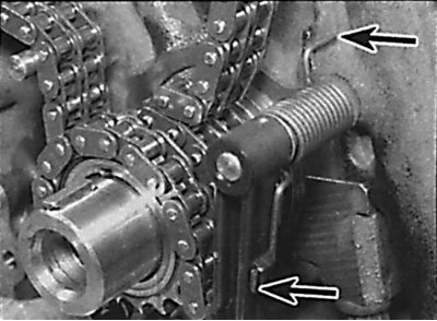
Arrangement of the ends of the oil pump drive chain tensioner spring
1. Install the segment key.
2. When installing a new sprocket, put alignment marks on it in the same places as on the old sprocket.
3. Heat the crankshaft sprocket to 50°C, align the groove in the sprocket hub with the key, and install the sprocket onto the crankshaft. Install the drive chain on the sprocket, matching the marks on the sprocket and chain.
4. Install bushing, spring and tensioner shoe onto pivot pin.
5. Pass the oil pump drive chain around the idler shoe, install the sprocket with the chain on the oil pump and secure with the bolt, tightening it to the required torque. The convex side of the sprocket should be on the oil pump side.
6. Check the correct installation of the oil pump drive chain tensioner spring (see fig. Arrangement of the ends of the oil pump drive chain tensioner spring).
7. Install the drive chain tensioner shoe and lower chain guide.
8. Install the oil pan.