
Attention! Sealant and new gaskets must be used when installing the drive chain top cover.
Removing
Unscrewing the bolts of the ignition distributor cover on models with a CIS fuel injection system
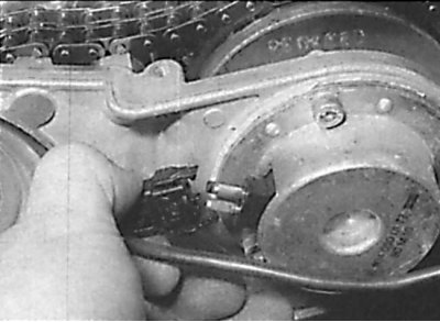
Removing the ignition distributor rotor
Unscrewing of a bolt of fastening of a rotor of the distributor of ignition
Removing the protective screen on models with a CIS fuel injection system
Unscrewing the plastic shield on models with a CIS fuel injection system
Removing the O-ring
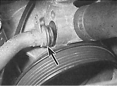
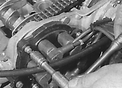
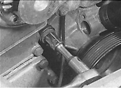
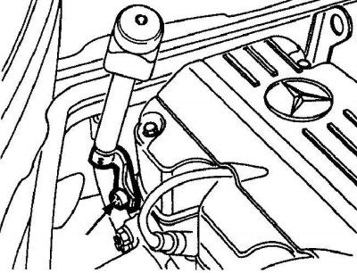
After disconnecting the coolant pipe from the water pump, remove the O-ring from the pipe.
Disconnecting the electrical connector from the camshaft position sensor
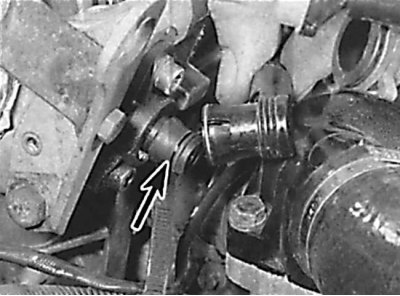
Removing the camshaft position sensor that controls the intake valves on models with a CIS fuel injection system
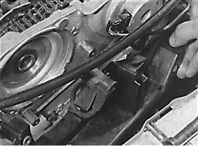
Unscrewing the bolt securing the auxiliary drive belt tensioner post to the drive chain cover on models with a CIS fuel injection system
Unscrewing the bolts securing the upper cover of the drive chain on models with a CIS fuel injection system
Removing the two timing chain cover bolts that also attach the engine mount
Removing the top drive chain cover

1. Remove the ground wire from the battery.
2. Drain the coolant from the cooling system.
3. Remove the cylinder head cover.
4. Disconnect the central high-voltage wire from the ignition distributor cover.
5. Unscrew the mounting bolts and remove the cover of the ignition distributor (see fig. Unscrewing the bolts of the ignition distributor cover on models with a CIS fuel injection system). Move the ignition distributor cover to the side without disconnecting the remaining high-voltage wires from it.
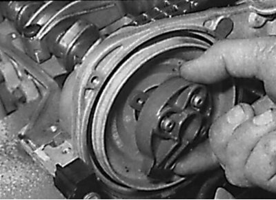
6. Unscrew the screws and remove the distributor rotor (see fig. Removing the ignition distributor rotor).
7. Unscrew the central bolt and remove the ignition distributor rotor drive (see fig. Unscrewing of a bolt of fastening of a rotor of the distributor of ignition).
8. Remove the protective shield and seal from the upper drive chain cover (see fig. Removing the protective screen on models with a CIS fuel injection system).
9. Remove the upper chain guide.
10. Remove the high voltage wire and unscrew the plastic shield from the base of the upper drive chain cover (see fig. Unscrewing the plastic shield on models with a CIS fuel injection system).
11. Remove the bolts securing the coolant supply pipe to the radiator fan and water pump. Disconnect the pipe from the water pump and move it to the side (see fig. Removing the O-ring).
12. Disconnect the electrical connector from the camshaft position sensor and the camshaft adjuster relay that controls the intake valves (see fig. Disconnecting the electrical connector from the camshaft position sensor, Removing the camshaft position sensor that controls the intake valves on models with a CIS fuel injection system).
13. Unscrew the intermediate pulley of the auxiliary drive belt.
14. Remove the bolt securing the high voltage wire bracket to the lower drive chain cover.
15. From the top cover of the drive chain, unscrew the plug located under the camshaft that controls the intake valves.
16. Remove the nut and bolt securing the brake booster vacuum hose bracket to the front engine mount.
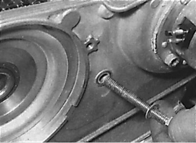
17. Remove the bolt securing the auxiliary drive belt tensioner to the drive chain cover (see fig. Unscrewing the bolt securing the auxiliary drive belt tensioner post to the drive chain cover on models with a CIS fuel injection system). Mark the location of the washers and gaskets for proper reinstallation.
18. On models with a cooling system elbow mounted in the center of the top drive chain cover, disconnect the hose from the elbow, unscrew the bolts, and remove the elbow.
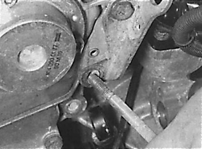
19. Unscrew bolts of fastening of the top cover of a driving chain. When doing this, keep in mind that the lower right bolt remains in the cover. The two bolts securing the upper drive chain cover also secure the front engine mount (see fig. Unscrewing the upper timing chain cover bolts on models with CIS fuel injection, Unscrewing the two timing chain cover bolts that also attach the engine mount).
20. Remove the upper drive chain cover along with the lower right bolt (see fig. Removing the top drive chain cover).
21. Remove the gasket from the groove in the top of the lower drive chain cover.
Installation
Installing a new camshaft seal that controls the exhaust valves
Installing a new gasket in the groove of the lower drive chain cover
1. Clean the mating surfaces of the upper timing chain cover and cylinder head.
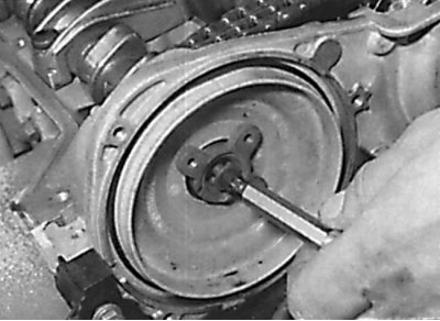
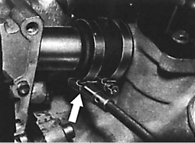
2. Replace the exhaust camshaft O-ring located in the timing chain cover (see fig. Installing a new camshaft seal that controls the exhaust valves).
3. Measure the installation depth of the O-ring, then using a screwdriver blade, pry the O-ring out of the upper timing chain cover.
4. Clean the O-ring seat in the top cover of the drive chain.
5. Using a tubular mandrel of the appropriate diameter, install a new O-ring into the seat to the previously measured depth.
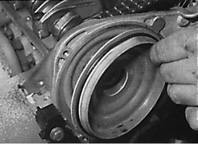
6. In order not to damage the working edges of the sealing ring when installing the drive chain cover, wrap the front end of the camshaft that controls the exhaust valves with adhesive tape.
7. Apply a layer of sealant to the junction of the top of the lower timing chain cover with the cylinder head.
8. Install a new gasket into the groove at the top of the lower drive chain cover. Lubricate the top side of the gasket (see fig. Installing a new gasket in the groove of the lower drive chain cover).
9. Apply a thin layer of sealant to the mating surfaces of the cylinder head and upper timing chain cover.
10. Install the lower right bolt to the timing chain cover, then install the cover to the cylinder head.
11. Install the remaining cover bolts and evenly and gradually tighten them to the required torque, starting with the bottom bolts.
12. Remove the adhesive tape from the front end of the camshaft that controls the exhaust valves.
13. Further installation is carried out in the reverse order of removal. Pour coolant into the cooling system.