
Top casing
Note: Sealant required for installation, new camshaft timing chain case gasket (see text) and a new O-ring for the cooling tube. It is also recommended to replace the camshaft oil seal.
Removing
1. Unfasten the radiator fan shroud and place it on top of the fan blades as described in Chapter 3.
2. Remove the camshaft cover as described in paragraph 4.
3. Where provided, unfasten the cap from the distributor cap. Disconnect the high voltage wires from the cover. Then unscrew the three mounting screws and remove the distributor cover. Take the cover aside along with the wires and the case.
4. Partially drain the cooling system as described in Chapter 1A.
5. Disconnect the heater hose from the tube running across the front of the cylinder head.
6. Turn away bolts of fastening, then remove a tube of cooling from the water pump and remove a tube. Remove the O-ring from the pump end of the tube.
7. Turn away three screws of fastening and remove the runner of the distributor.
8. Loosen the bolt and remove the drive bush (see fig. 6.8). Unfasten the plastic cover on the front of the upper chain cover.
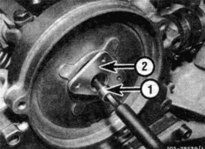
Pic. 6.8. Pic. 17.8. Scheme of connecting system devices (68-pin connector)
Loosen the drive bushing bolt (1) and remove the bushing (2)
9. Turn away bolts of fastening of the top casing of a chain and remove a casing. The casing is installed using sealant and is located on the dowels. Therefore, it may be necessary to tap the casing at the rear with a plastic hammer to separate it from the cylinder head.
10. Remove the gasket from the groove in the top of the lower target housing.
Installation
11. Begin installation with thorough cleaning of the mating surfaces of the upper and lower casings of the drive chain and cylinder head. Remove all traces of old sealant.
12. It is recommended to replace the camshaft seal in the chain case as follows.
- A) Pry off the old cuff with a screwdriver.
- b) Clean the cuff seat in the casing.
- V) Hammer in a new cuff (dry) into place using a pipe or wrench head so that the collar is flush with the outer surface of the casing.
13. A piece of thin polyethylene or adhesive tape around the front camshaft flange will prevent damage to the collar when installing the casing.
14. Apply a small amount of sealant to the connections between the lower chain case and cylinder head, then install a new gasket in the groove at the top of the lower case (see fig. 6.14).
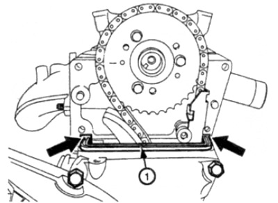
Pic. 6.14. Apply sealant (shown by arrow) on the connection of the lower chain cover with the cylinder head, then install a new gasket (1).
15. Apply sealant to the surface of the upper casing mounted on the cylinder head.
16. Lubricate the lips of the camshaft collar with clean engine oil, then slide the casing into place through the camshaft, making sure that the casing is aligned with the cylinder head keys.
17. Install the casing mounting bolts, then tighten the bolts to the required torque, starting with the bottom two.
18. Gently wipe off any excess sealant with a lint-free cloth.
19. Where used, remove the polyethylene or adhesive tape from the camshaft.
20. Where provided, install the cover on the front of the upper timing chain case, then install the runner drive bushing, making sure the groove on the bushing aligns with the boss on the camshaft. Install the bushing bolt and tighten to the correct torque.
21. Install the slider and tighten the mounting screws.
22. Install the cooling tube to the water pump using a new o-ring, then tighten the tube mounting bolts.
23. Connect the cooling hose to the tube.
24. Establish a cover of the distributor and connect wires of the coil of ignition.
25. Install the camshaft cover as described in paragraph 4.
26. Install the radiator fan shroud as described in Chapter 3.
27. Fill the cooling system as described in Chapter 1A.
Bottom casing
Installation will require sealant, a new bracket bolt seal (see text). A new oil feed tube O-ring may be required and a new front crankshaft seal is recommended.
Removing
28. Disconnect the negative battery terminal.
29. Raise the hood to the fully open position.
30. Where provided, remove the engine shield as described in Chapter 11.
31. Remove the air cleaner as described in Chapter 4.
32. Remove the heatsink and fan blades as described in Chapter 3.
33. Loosen the radiator fan clutch, water pump mounting bolts, and suspension leveling pump pulley bolts, then remove the accessory drive belt as described in Chapter 1A.
34. Turn away bolts of fastening and remove pulleys of belts.
35. Remove the crankshaft pulley/vibration damper and hub as described in paragraph 5.
36. Turn away bolts of fastening, then remove a tube of cooling which passes across a forward part of a head of cylinders from the water pump. Remove the O-ring from the end of the tube. Move the handset away from the work area.
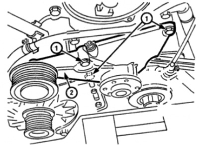
37. Remove the nut and remove the bolt from the front of the rigging bracket on the front of the engine (see fig. 6.37).
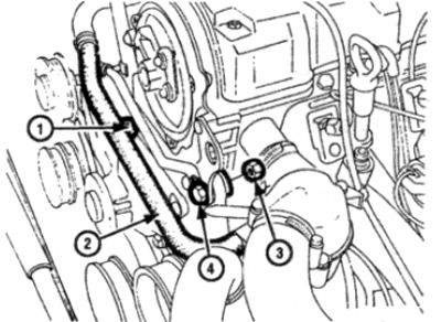
Pic. 6.37. Coolant pipe and engine rigging bracket parts
1 Coolant pipe bolt
2 Cooling tube
3 Nut
4 Bolt
38. On models with adjustable suspension, loosen the hose clamp and disconnect the hydraulic hose from the tube on the front left side of the cylinder head. Be prepared for fluid spillage and cover the open ends of the tube and hose to prevent dirt from entering and fluid loss.
39. Remove the upper drive chain cover as previously described.
40. Loosen the center bolt securing the suspension leveling pump bracket, then remove the remaining three bracket mounting bolts (hold the nut on the back of the bolt) (see fig.6.40). Remove washers.
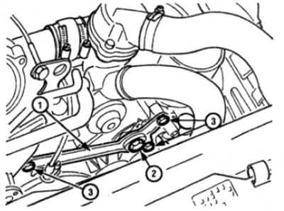
Pic. 6.40. Suspension leveling pump mounting bracket
1 support bracket
2 Central bolt
3 Mounting bolts
41. Rotate the bracket away from the drive chain housing.
42. Turn away two bolts of fastening of the pump of system of adjustment of a suspension bracket to a basic arm, then turn away the pump aside from the engine.
43. Remove the mounting bolts and remove the radiator fan pulley bracket from the chain cover (see fig. 6.43).
Pic. 6.43. Loosen the mounting bolts (1) and remove the radiator fan pulley bracket (2)
44. Remove the fastening nut and remove the crankshaft position sensor from the front of the camshaft drive chain casing from the bracket. Where present, release the wires from the clamps and holders and slide the sensor out of the work area.
45. Disconnect the alternator connector.
46. Turn away four bolts of fastening of an arm of the generator to the engine and the generator then remove an arm and the generator.
47. Remove the tensioner as described in paragraph 8.
48. Working from below the engine, unscrew the bolts securing the pallet to the drive chain housing (see fig. 6.48). Remember the location of the bolts as they vary in length. On adjustable suspension models, move the fluid hose (fixed to the pallet with bolts securing the casing to the pallet) away from the work area.
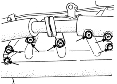
Pic. 6.48. Turn away bolts (shown by arrow) attaching the pallet to the chain cover
49. Remove the remaining casing mounting bolts, remembering their location, as they vary in length (see fig. 6.49].
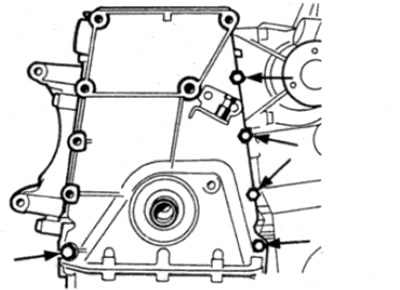
Pic. 6.49. Loosen the remaining chain cover bolts (shown by arrow)
50. Gently pull the casing forward from the dowels in the cylinder block. If the casing is stuck, lightly tap the edges with a wooden mallet - do not use a lever between the mating surfaces of the casing and cylinder block.
Note: Be careful not to damage the pan gasket when removing the cover.
Installation
51. Begin installation by thoroughly cleaning the mating surfaces of the lower drive chain housing and cylinder block and upper housing. Remove all traces of old sealant.
52. Carefully check the condition of the pan gasket. If the gasket is damaged during removal, the pan must be removed to replace the gasket as described in paragraph 11.
53. It is recommended to replace the crankshaft seal in the chain housing as follows.
- A) Pry off the old cuff with a screwdriver.
- b) Clean the cuff seat in the casing.
- V) Hammer in a new cuff (dry) into the socket using a pipe or a key head so that the cuff rests against the shoulder on the casing.
54. A piece of thin polyethylene or adhesive tape around the front crankshaft flange will prevent damage to the cuff when installing the casing.
55. Replace the seal located at the location of the bottom bolt that secures the radiator fan bracket to the chain cover.
56. Apply sealant to the surface of the casing installed on the cylinder block.
57. Lubricate the edges of the crankshaft seal with clean engine oil, then slide the casing into place through the crankshaft, making sure that the casing is aligned with the keys of the cylinder block. Be careful not to damage the collar edges when installing the cover.
58. Install the casing mounting bolts shown in fig. 6.49, making sure that the bolts are in place, then tighten them to the required torque.
59. Where used, remove adhesive tape from crankshaft.
60. Install the shroud-to-sump bolts, making sure the suspension adjustment hose is in place, then tighten the bolts to the correct torque.
61. Install the chain tensioner as described in paragraph 8.
62. Install the generator and support bracket, then connect the generator wires.
63. Install the crankshaft position sensor to the bracket on the chain cover and tighten the mounting nut.
Note: If a new chain cover is being installed, check the position of the sensor as described in Chapter 4.
64. Install the cooling fan bracket and tighten the mounting bolts to specification.
65. Rotate the power steering/suspension leveling pump onto the support bracket, then install and tighten the mounting bolts.
66. Apply sealant to both sides of the shroud at the location of the power steering pump bracket/suspension leveling bracket bolt.
67. Turn the pump bracket into place, then install and tighten the mounting bolts, making sure that the washers are installed. Tighten the center bolt.
68. Install the upper chain case as described earlier in this paragraph.
69. Where necessary, connect the self leveling hose to the tube in front of the cylinder head.
70. Install the engine mount bracket bolt and nut.
71. Connect a cooling tube to the water pump, using a new sealing ring, then wrap fastening bolts.
72. Install the crankshaft pulley/vibration damper and hub as described in paragraph 5.
73. Install the accessory drive belt pulleys and tighten the mounting bolts.
74. Install the accessory drive belt as described in Chapter 1A and tighten the pulley bolts.
75. Install the fan blades and heatsink as described in Chapter 3.
76. Install the air cleaner.
77. Where provided, install engine protection.
78. Fill the cooling system as described in Chapter 1A.
79. Check and, if necessary, add engine oil and, where necessary, fluid to the power steering system / suspension leveling system, as described in section "Weekly check".
80. Connect the negative terminal of the battery.