
Basic provisions
1. The timing gear is part of the camshaft bearing caps. The cams are mounted on separate short shafts that are seated in the camshaft bearing caps. Each cover has one exhaust and one intake cam.
2. Hydraulic tappets are mounted on the cams and supplied with oil through holes in the cams.
Removing
Warning: There have been many modifications to the camshaft, cam parts and lubrication tubes produced in the production of engines. Certain combinations of new and old parts do not match and engine damage can occur if incompatible parts are installed together. From this point of view, when replacing parts, it is recommended to seek the advice of a Mercedes-Benz dealer to be sure that the necessary parts are installed.
3. Remove the air cleaner as described in Chapter 4.
4. Remove the camshaft sprocket as described in paragraph 6.
5. Remove the mounting bolts and remove the oil spray tube from above the camshaft bearing caps. Note that the tube, depending on the model, can be fastened with two or three bolts. where it is installed. remove the mounting plate from the central mounting bolt.
6. Check up presence of designations on cams of pushers and covers of bearings of a cam-shaft. Caps are usually numbered 1 to 6, counting from the end of the cylinder head with the camshaft sprocket on the exhaust manifold side. The corresponding mark is cast on the cylinder head under the camshaft. If there are no marks, make them with a core.
7. Gradually loosen the camshaft cover bolts (each cover is attached with four bolts) in diagonal sequence (see fig. 9.7).
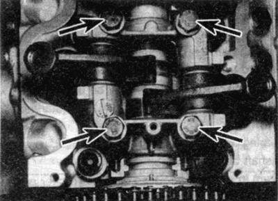
Pic. 9.7. Bolts of fastening of a cover of the bearing of a raspreval No 1
8. Remove the bearing cap/cam assemblies. Note that the lids are mounted on pins - if they are stuck, lightly tap the lids with a mallet.
Advice. Store contact pads in a divided box with eight compartments labeled 1 to 6 for intake valves and 1 to 6 for exhaust valves.
9. Remove the contact pads of the pushers from the valve stems, keeping them in strict order. You can't swap parts.
10. Carefully remove the shaft from the cylinder head. Where fitted, remove thrust washers from front bearing against shaft axial free play.
Disassembly, inspection and assembly
Distribution led
11. Check the shaft bearings and cams for wear, scoring, deep scratches or pitting. If found, the shaft must be replaced. Any damage of this nature indicates a blockage of the lubrication channel either in the cylinder head, or in the cam assembly, or in the oil spray tube. To find out the reason, you need to carefully check the details. When replacing the camshaft, the cams also change at the same time.
Gear driven cams
12. With the camshaft bearing caps removed, the cams can be removed from the caps by pulling out the short cam shafts. Before removing the cams, check for the presence of identification marks and, if any, apply it (designate cams from 1 to 6 for intake valves and from 1 to 6 for exhaust). Do not swap parts. Pay attention to how the cams are mounted on the shafts.
13. Screw an M8 bolt into the cam shaft, then use the bolt to pull out the cam shaft by hand. When the shaft is removed, the cam can be removed. Parts can be stored in a box divided into compartments along with contact pads of pushers (see fig. 9.13).
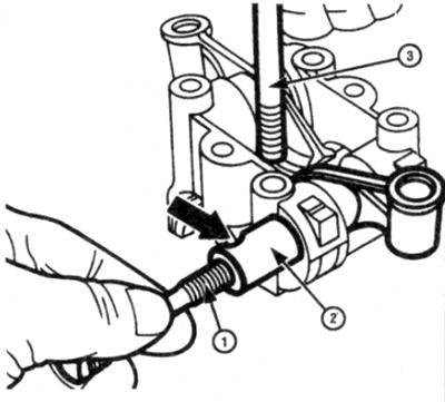
Pic. 9.13. Use M8 bolt (1) to pull out the cam shaft (2)
14. Check up wear of contacting pillows of pushers. Check how the cams are installed on their shafts. If visible wear or damage is found, it is recommended to replace the parts as a set.
15. Thoroughly clean the parts before installation.
16. Lubricate the mating surfaces of the cams and shaft, then following the notes below, install the shaft and cam onto the appropriate bearing cover.
- A) If working parts are installed, make sure they are installed in their original places.
- b) Make sure each pusher fits properly onto the shaft as noted prior to removal.
- V) Make sure the camshaft bearing cap bolt groove on each shaft is aligned with the camshaft bearing cap bolt hole.
- G) Use an MB bolt to install each cam shaft into the bearing cap.
17. To remove the follower from the cam, insert a suitable drift into the hole in the top of the cam and push the follower out of the cam (see fig. 9.17).
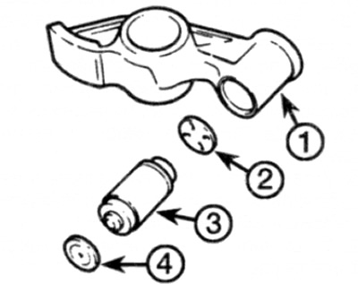
Pic. 9.17. Valve lifter/cam assembly
1 Cam
2 Adjusting washer
3 Valve tappet
4 Contact pad
18. Remove the shim from the pusher housing on the cam.
19. Store the valve lifters and washers in a strict order so that they can be installed in their places.
20. Check up wear of pushers of valves and washers. If wear or damage is found, replace them.
21. The operation of the valve lifters can be checked as follows (see fig. 9.21).
- A) Hold the valve lifter vertically.
- b) Fill the supply chamber at the top of the tappet with clean engine oil.
- V) Insert a piece of thin wire (diameter 1.5 mm) through the hole in the center of the tappet and push down on the valve ball until it stops. Then release the ball. Repeat these steps until the working chamber at the base of the pusher is filled with oil.
- G) Firmly press down on the top of the pusher piston for approximately 10 seconds using a blunt object such as a hammer handle.
- d) If the pusher piston moves down, then the entire pusher set needs to be replaced.
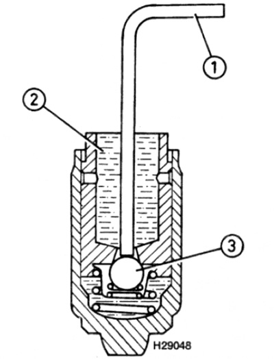
Pic. 9.21. Checking the action of the valve lifter
1 Wire with a diameter of 1.5 mm
2 Oil supply chamber
3 ball valve
22. The design of hydraulic tappets is such that the amount of play or clearance they can compensate for is limited. Basically, this is determined by the small size of the nodes. To keep the gap at a minimum level and to ensure that the pushers work within operating limits, shims of various thicknesses are installed.
23. Under normal conditions, the tappets are automatically adjusted to provide the required clearance between the cam and the valve stem.
24. However, if the parts are significantly worn or after replacing the camshaft, cams, valves or tappets themselves, the valve assembly becomes noisy in operation, the gaps may have gone beyond automatic compensation. In this case, it is necessary to replace the adjusting washer with a different size.
25. To determine the required thickness of the shim, a special indicator device and a collar are required. Have the work done by a Mercedes-Benz dealer.
26. It is recommended to install valve lifters with cams already mounted on the cam shafts. This will reduce installation time and reduce the possibility of valve lifters draining oil if prepared as described below.
27. Each valve must be filled with oil prior to installation. To do this, hold the assembly upright and fill the chamber with clean engine oil. Using a piece of thin wire inserted through the chamber, press down on the ball valve so that the oil can drain into the working chamber (see fig. 9.21). At the same time, push the pusher up to the stop. Repeat these steps several times until the oil stops leaving the working chamber.
28. Install the shim onto the cam body with the oil notches facing the pushrod, then insert the pushrod. Press the pusher until it contacts the circlip. The bearing cap/cam assembly can then be installed on the motor.
Installation
29. Check that the thrust washers are correctly positioned on the front bearing.
30. Lubricate the camshaft and bearings in the bearing caps and cylinder head with clean engine oil, then lay the camshaft in place on the cylinder head. Rotate the camshaft so that the TDC pin or hole on the flange at the front of the camshaft points vertically upwards - see paragraph 3.
31. Install pusher contact pads on the appropriate valve stems.
32. Install the bearing caps in their positions with identification numbers on the side of the exhaust manifold.
33. Install the cover bolts and tighten them with the required force gradually, in a diagonal sequence.
34. Check the condition of the oil spray tube, paying special attention to the spray holes. If the holes are out of shape or damaged, replace the tube.
35. Check that the crankshaft alignment mark is aligned with the TDC position of the 1st cylinder (see paragraph 3), then install the camshaft sprocket as described in paragraph 8.
36. Install the air cleaner.